In this article, you will learn what is a displacement transducer, the types of transducers, their advantages, disadvantages, and their applications.
Contents
What is a Displacement Transducer?
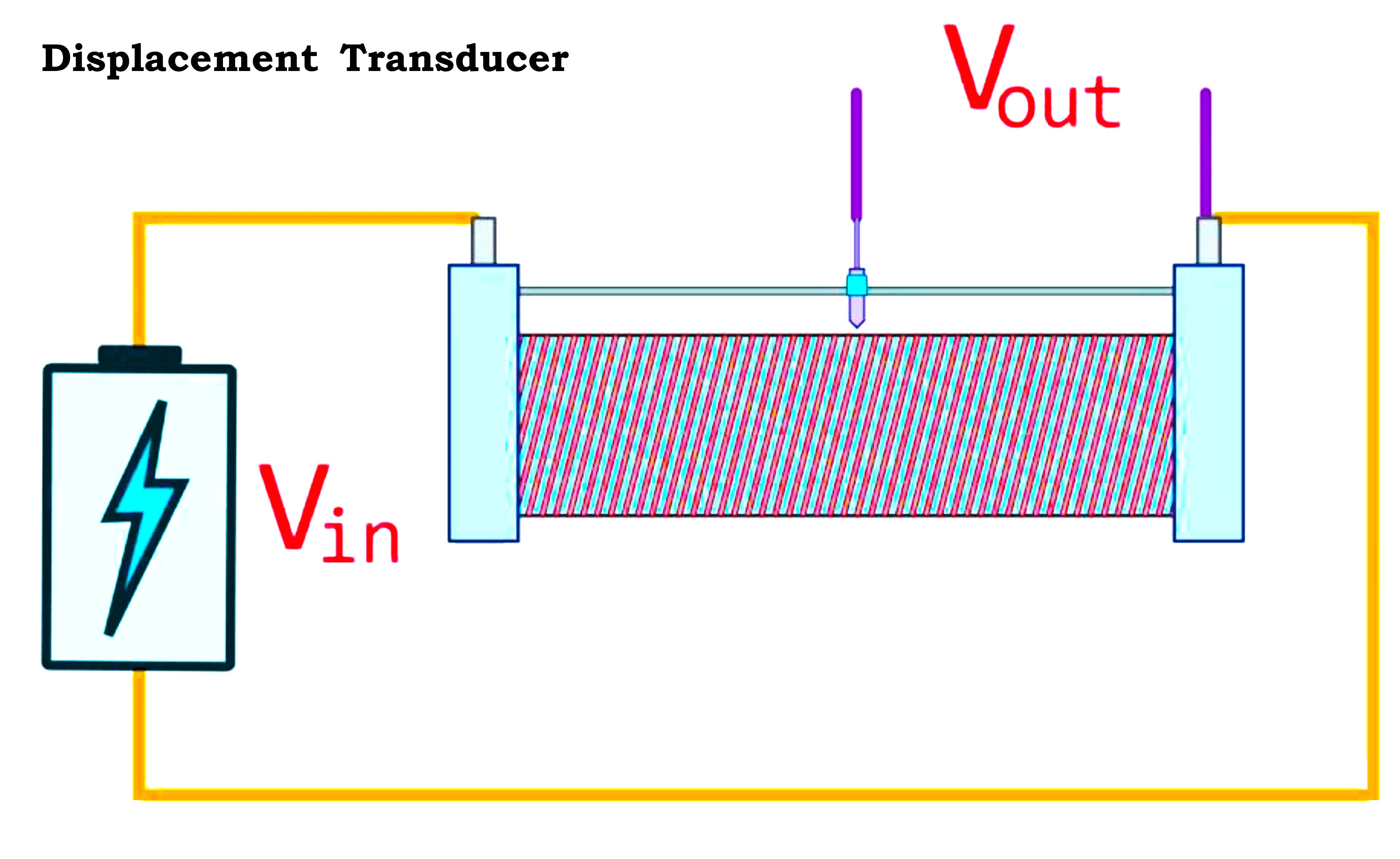
- A displacement transducer converts the motion of an object or machine into electromagnetic, magneto-electric, or electrostatic signals.
- The signals received from these transducers are read and interpreted into data.
- Displacement transducers are classified based on a motion such as linear & rotary.
- This transducer helps to measure the physical distance between the sensor & a target.
- Generally, these transducers measure static & dynamic displacements & for measuring the vibration of an object.
- The displacement value varies from micro inches to a few feet.
- The working principle of displacement transducers is based on reliable inductive measurement.
- These transducers are very easy to use, & rugged, to attain high precision. Displacement transducers yield reliable measurement results in various areas of production, research & development.
- These transducers are used for both direct and indirect displacement measurements.
Types of Displacement Transducer
The basic types of displacement transducers are mentioned below.
- Strain Gauge
- Resistive Transducer
- Capacitive Transducer
- Inductive Transducer
- LVDT
- RVDT
Strain Gauge
- A strain gauge displacement transducer changes physical quantities into mechanical strain.
- This mechanical strain is changed into a proportional electrical signal
- The strain gauges are mounted on the elastic body.
- A strain gauge-type displacement transducer is mainly used to measure the displacement in the range of 0 to 10 mm.
- The length of the Strain Gauge transducer is short compared to LVDT & is free from electromagnetic effects.
- This strain gauge transducer is highly stable & reliable.
Resistive Transducer
- A resistive transducer is known as a variable resistance transducer.
- This works on the principle of variable resistance transduction.
- It consists of resistive elements along with movable contact.
- This transducer is the most frequently used displacement transducer.
- The motion may be translational rotational or helical or a combination of either motion.
- This measures various physical quantities like pressure, displacement, force, temperature, and vibrations and converts them into an equivalent electrical signal.
Capacitive Transducer
- A capacitive transducer is a type of passive transducer.
- Capacitive transducers detect motion, chemical composition acceleration, electric field, pressure, and so on.
- Due to the applied voltage across the capacitor plate equal & opposite charges are generated on transducer plates separated by the dielectric material.
- This transducer works by using external power.
- This transducer measures pressure, displacement, movement, force, velocity & other parameters.
- This transducer works on the principle of variable capacitance.
- The capacitance of this transducer varies due to some factors like dielectric constant, & overlapping of plates.
Inductive Transducer
- An inductive transducer is another type of displacement transducer compared to resistive and capacitive transducers.
- An inductive transducer works on the principle of transduction or electromagnetic induction.
- Measurement of some necessary physical quantities such as displacement, force, velocity, pressure, acceleration, torque, mutual inductance, or self-inductance varies.
- Inductive Transducer is further classified as a Linear Variable Differential transducer or Rotary Variable Differential Transducer.
- But LVDT is considered the best example of an Inductive Transducer.
Linear Variable Differential Transformer (LVDT)
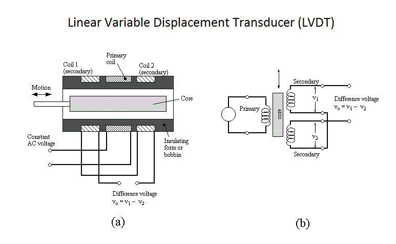
- The Linear Variable Differential Transformer (LVDT) is one type of displacement transducer.
- It is an electromechanical device.
- This coil generates proportional output voltage relative to the displacement of the iron core and transformer.
- This transducer consists of three coils symmetrically spaced with each other.
- Here the primary coil is the center coil & secondary coils are the remaining two coils.
- The secondary windings are identical concerning the turning number and placement of both sides of the primary winding.
- These coils are mainly connected in series & positioned equally around the main coil.
- A sine volt is used to excite the primary coil.
- A movable core generates an electrical signal in proportion to its displacement.
- When the core is in the middle a sinusoidal voltage appears across two secondaries.
Rotary Variable Differential Transducer (RVDT)
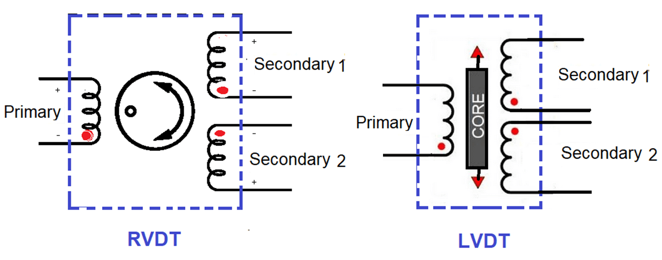
- A rotary variable differential transducer (RVDT) is used to measure rotational angles.
- It is an electromechanical transducer that gives a variable AC output voltage in linear proportionality to the angular displacement.
- This transducer also works on the LVDT principle both RVDT and LVDT work similarly.
- RVDT transducer consists of two windings, such as one primary winding and two secondary windings.
- LVDT uses a flexible cylindrical iron core, whereas RVDT uses a rotary ferromagnetic cam-type core.
- RVDT senses the angular displacement and converts it to the proportional electrical signal.
- RVDT features linearity over +40 or -40 degrees.
- The sensitivity of RVDT ranges from 2mV to 3mV per degree of rotation.
Circuit Diagram of Displacement Transducer
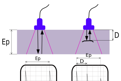
The displacement transducer shown below diagram is an inductive transducer.
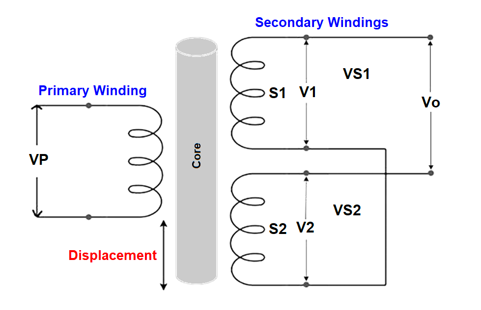
- This circuit measures displacement with an Inductive transducer.
- The transformer consists of one primary winding & two secondary windings.
- The endpoints of two secondary windings are linked to each other.
- Here, both these secondary windings are connected in a series position.
- The Primary voltage “VP” is applied at the primary winding of the transformer.
- Let, ????????1 & ????????2 be voltage developed across every secondary winding of the transformer.
- Finally, the output voltage ‘V0’ is generated across the first points of secondary windings.
- So the output voltage at the secondary of the transformer is given as V0 = VS1 – VS2.
- The output voltage generated at the secondary of the transformer has dissimilarity between VS1 & VS2 since the transformer is the differential transformer.
- If the core is placed at the center, then the induced voltages across two windings S1 & S2 are equivalent, so output voltage becomes zero (V0=0) hence there is no displacement at this condition.
- If the core is placed above the center, then the induced voltages generated across S1 are maximum (V1>V2).
- Similarly, if the core is placed below the center then the induced voltages generated across S1 are maximum (V2>V1).
- So in above both cases, we have two displacements one is upward & other is downward.
- Hence, the magnitude of output voltage ‘V0’ is in proportion to the core position relative to the center.
- To measure the displacement of the body we must connect it to the central core.
- The middle point of the core varies when the body shifts in a straight line which makes the output voltage ‘V0’ vary accordingly.
Advantages of Displacement Transducer
The advantages of displacement transducers are mentioned below.
- Linearity is excellent.
- Accuracy is extremely high in wide temperature ranges.
- Resolution is up to 0.01 µm.
- They are tolerant to high magnetic fields.
- The design is strong with excellent stability
- These transducers can be fixed in any direction
- Power consumption is very less.
- hysteresis loss is low
- This transducer has no or minimum friction.
- High measurement range.
- Sensitivity is high
- Alignment & maintenance is easy.
Disadvantages of Displacement Transducer
The disadvantages of displacement transducers are mentioned below.
- Requires very high displacement to generate high voltage.
- Requires shielding due to being more responsive to the magnetic field.
- The performance is affected by vibrations & temperature changes.
- An external demodulator is required to generate DC output.
- Limited dynamic response.
Applications of Displacement Transducer
Displacement transducers are used in the following applications.
- Measurement of relative movement between the sensor tip & the rotating shaft.
- CNC machines to measure displacement.
- To measure the thickness of rolled metal sheets
- For measuring force, acceleration & pressure
- Within flight control systems
If you liked this article, then please subscribe to our YouTube Channel for Instrumentation, Electrical, PLC, and SCADA video tutorials.
You can also follow us on Facebook and Twitter to receive daily updates.
Read Next:
- Hazard Identification
- Smart Sensors in Industry
- Delta HMI and VFD Logic
- Motor Temperature Sensors
- MOVE Instruction in PLC