Inst ToolsInst ToolsInst Tools
  • Courses
  • Automation
    • PLC
    • Control System
    • Safety System
    • Communication
    • Fire & Gas System
  • Instrumentation
    • Design
    • Pressure
    • Temperature
    • Flow
    • Level
    • Vibration
    • Analyzer
    • Control Valve
    • Switch
    • Calibration
    • Erection & Commissioning
  • Interview
    • Instrumentation
    • Electrical
    • Electronics
    • Practical
  • Q&A
    • Instrumentation
    • Control System
    • Electrical
    • Electronics
    • Analog Electronics
    • Digital Electronics
    • Power Electronics
    • Microprocessor
  • Request
Search
  • Books
  • Software
  • Projects
  • Process
  • Tools
  • Basics
  • Formula
  • Power Plant
  • Root Cause Analysis
  • Electrical Basics
  • Animation
  • Standards
  • 4-20 mA Course
  • Siemens PLC Course
Reading: Multiple Position Calibration of Temperature Chamber
Share
Font ResizerAa
Inst ToolsInst Tools
Font ResizerAa
  • Courses
  • Design
  • PLC
  • Interview
  • Control System
Search
  • Courses
  • Automation
    • PLC
    • Control System
    • Safety System
    • Communication
    • Fire & Gas System
  • Instrumentation
    • Design
    • Pressure
    • Temperature
    • Flow
    • Level
    • Vibration
    • Analyzer
    • Control Valve
    • Switch
    • Calibration
    • Erection & Commissioning
  • Interview
    • Instrumentation
    • Electrical
    • Electronics
    • Practical
  • Q&A
    • Instrumentation
    • Control System
    • Electrical
    • Electronics
    • Analog Electronics
    • Digital Electronics
    • Power Electronics
    • Microprocessor
  • Request
Follow US
All rights reserved. Reproduction in whole or in part without written permission is prohibited.
Inst Tools > Blog > Calibration > Multiple Position Calibration of Temperature Chamber

Multiple Position Calibration of Temperature Chamber

This article covers multiple position calibration procedure of temperature ovens. Also called as Mapping of Temperature Chamber.

Last updated: September 28, 2022 3:24 pm
Saurabh Vaidya
Calibration Temperature Measurement
1 Comment
Share
5 Min Read
SHARE

This article covers Multiple Position Calibration of Temperature Chamber.

Contents
Examples of Placement of Temperature SensorCalibration Procedure of Temperature Chamber – Multiple Position

Different Temperature chambers are Oven, Incubator, Refrigerator, Freezer, Walk-in Chamber, etc.

Large effective Volume should not be calibrated for a Single Position. Only Multi-Position (Mapping) is allowed.

Multi-Position Calibration of Temperature Bath is also called as Mapping of Temperature Chamber.

For Temperature Mapping, N-type Thermocouple is also acceptable along with RTD Sensor.

Placement of Temperature Sensor in Multi-Position Calibration depends upon Volume of Temperature Chamber and user-defined according to the position of sample material store in Oven, Incubator, etc.

Examples of Placement of Temperature Sensor

Placement of Temperature Sensor in Walk-in Chamber

The below figure shows a temperature chamber with a capacity of 27 temperature sensors.

Temperature Sensor in Walk-in Temperature Chamber
Figure 1: Temperature Chamber Sensors Position

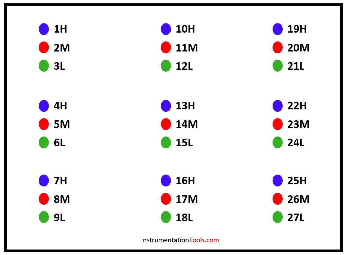
For example, consider the letters “1H” from the above picture.

1 – defines the number of Sensor,

H – Defines position i.e. Higher Shelf,

M – Defines position i.e. Middle Shelf,

L – Defines position i.e. Lower Shelf.

Placement of Temperature Sensor in Oven, Incubator. (Small Chamber)

The below figures show different types of temperature sensor placements in a temperature chamber.

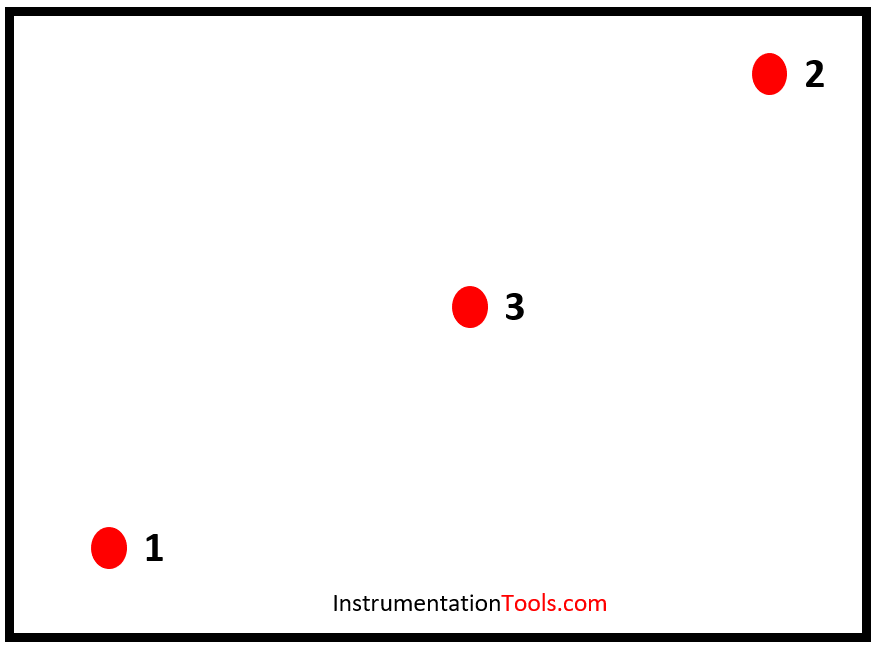
Figure 2 has five sensor placements and figure 3 has three sensor placements.

Temperature Sensors in Incubator
Figure 2: Temperature Sensors Placement in Incubator
Examples of Placement of Temperature Sensor
Figure 3: Temperature Sensors Placement in Incubator

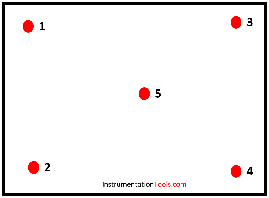
To adequately map each storage shelf, a suggested pattern is five sensors per shelf, one in each of the four corners and one in the center as shown in figure 2.

Another common pattern used for chambers is three sensors in diagonal patterns on each shelf as shown in figure 3.

Patterns of placement of temperature sensor is user defined.

Chambers should be mapped both empty and loaded with the actual product or with the simulated product.

Calibration Procedure of Temperature Chamber – Multiple Position

The following calibration procedure will help you to calibrate the temperature bath with a multiple position method.

Step 1:

Insert the Master RTD Sensor/Thermocouple into the Temperature Chamber (UUC) according to Fig 1, 2, or 3 or according to user requirement and size of the chamber.

Here we need Master RTD Sensor/Thermocouple more than 1 quantity as this is multi position calibration.

For Example:

Calibration according to Figure 1 needs 27 sensors. It’s not feasible to use 27 multi-function calibrators to read these sensors’ temperature readings. So we use a data logger.

Connect all these temperature sensors to a data logger to read the sensor output in temperature units like degrees Celsius. The data logger is simplified equipment to connect all the sensors and to read their respective readings easily.

Step 2:

Decide the calibration points after discussing with the end user.

The working range should be completely covered in these calibration points such as Minimum, Middle, and Maximum working points.

For e.g. – The calibration points of the Incubator are 25, 38, 50 degrees Celsius.

Step 3:

Set the first calibration point on Temperature Chamber (UUC).

Allow temperature chamber to attend the desired set temperature and Stabilize at first calibration point.

Allow UUC and Master indicators reading to stabilize at the setpoint.

Step 4:

Note down the UUC temperature reading displayed on indicator of Temperature chamber and Master RTD Sensor/Thermocouple reading.

Note- Temperature Chamber shows two readings, Set temperature and Actual Temperature, note down Actual temperature reading.

Take 5 readings at the single setpoint from all the locations of the Master Sensor.

Calculate the average reading for each calibration point at each location.

For e.g. Location-1 readings are 25.02, 25.06, 25.13, 25.04, and 25.08, average is 25.06

Do these calculations for each location for every calibration point.

Step 5:

Repeat Step 3 and Step 4 for other calibration points.

i.e., do the same calibration step for 28, 35, 50 degrees Celsius.

Record all the readings in your calibration sheet.

If you liked this article, then please subscribe to our YouTube Channel for Instrumentation, Electrical, PLC, and SCADA video tutorials.

You can also follow us on Facebook and Twitter to receive daily updates.

Read Next:

  • Tolerance, Uncertainty, and Error
  • Calibration Standard DKD-R-6-1
  • Impulse Line Pressure Testing
  • Calibration of Pressure Transmitter
  • Calibration of Measuring Instrument
Don't Miss Our Updates
Be the first to get exclusive content straight to your email.
We promise not to spam you. You can unsubscribe at any time.
Invalid email address
You've successfully subscribed !

Continue Reading

How to calculate the tolerance of a RTD sensor
Types of Thermocouples
Resistance Temperature Detectors (RTD) Construction
Temperature Sensor Failure
Why we use Wheatstone bridge in RTD?
What is RTD Accuracy ?
Share This Article
Facebook Whatsapp Whatsapp LinkedIn Copy Link
Share
1 Comment
  • Meiyana sundharam S says:
    June 16, 2023 at 4:04 pm

    Pls specify if any related standards that claims this number of points mentioned in article

    Reply

Leave a Reply Cancel reply

Your email address will not be published. Required fields are marked *

Stay Connected

128.3kFollowersLike
69.1kFollowersFollow
210kSubscribersSubscribe
38kFollowersFollow

Categories

Explore More

How RTD Measuring the Temperature
Calculate Temperature Transmitter Output
Installation and Calibration of Level Transmitter
Foundation Fieldbus Temperature Transmitter Configuration
Automated Calibration
Methods of Measurement
Closed tank DP Level Transmitter with wet leg Zero elevation Calibration
Thermowell Design Guidelines

Keep Learning

Thermocouples Calibration Errors

Thermocouples Sources of Error

Thermocouple Software compensation

Thermocouple Software compensation

3 Wire RTD Connections

RTD Sensor Connections

How to calculate Thermocouple Temperature by measuring the output millivoltage

thermocouple types

What is a Thermocouple ?

How to Calibrate Load Cells

How to Calibrate Load Cells in Weighing Applications?

Vibration Probe Field Setting Procedure

How to do calibration checks of vibration Probe, extension cable and vibration monitor

Thermocouple Temperature Measurements Errors

Thermocouple Temperature Measurement Errors

Learn More

Ladder Logic of Motor Forward and Reverse

PLC Programming Example for Motor Forward and Reverse Control

Mass Spectrometer Questions and Answers

Surface Spectroscopic Techniques

magnetic flow meter parts

What is a Magnetic Flow Meter?

Critical Factors to Consider for Engineering Students to Ensure a Smooth Path

Critical Factors to Consider for Engineering Students to Ensure a Smooth Path

Level Measurement Objective Questions

Level and Density Measurement Objective Questions

Why Damper windings used in synchronous motors

optical fibers terminations

Fiber Optic Data Communication

Polarization Index (PI) Test

Polarization Index (PI) Test and DA Test

Menu

  • About
  • Privacy Policy
  • Copyright

Quick Links

  • Learn PLC
  • Helping Hand
  • Part Time Job

YouTube Subscribe

Follow US
All rights reserved. Reproduction in whole or in part without written permission is prohibited.
Welcome Back!

Sign in to your account

Username or Email Address
Password

Lost your password?