Inst ToolsInst ToolsInst Tools
  • Courses
  • Automation
    • PLC
    • Control System
    • Safety System
    • Communication
    • Fire & Gas System
  • Instrumentation
    • Design
    • Pressure
    • Temperature
    • Flow
    • Level
    • Vibration
    • Analyzer
    • Control Valve
    • Switch
    • Calibration
    • Erection & Commissioning
  • Interview
    • Instrumentation
    • Electrical
    • Electronics
    • Practical
  • Q&A
    • Instrumentation
    • Control System
    • Electrical
    • Electronics
    • Analog Electronics
    • Digital Electronics
    • Power Electronics
    • Microprocessor
  • Request
Search
  • Books
  • Software
  • Projects
  • Process
  • Tools
  • Basics
  • Formula
  • Power Plant
  • Root Cause Analysis
  • Electrical Basics
  • Animation
  • Standards
  • 4-20 mA Course
  • Siemens PLC Course
Reading: Single Position Calibration of Temperature Bath
Share
Notification Show More
Font ResizerAa
Inst ToolsInst Tools
Font ResizerAa
  • Courses
  • Design
  • PLC
  • Interview
  • Control System
Search
  • Courses
  • Automation
    • PLC
    • Control System
    • Safety System
    • Communication
    • Fire & Gas System
  • Instrumentation
    • Design
    • Pressure
    • Temperature
    • Flow
    • Level
    • Vibration
    • Analyzer
    • Control Valve
    • Switch
    • Calibration
    • Erection & Commissioning
  • Interview
    • Instrumentation
    • Electrical
    • Electronics
    • Practical
  • Q&A
    • Instrumentation
    • Control System
    • Electrical
    • Electronics
    • Analog Electronics
    • Digital Electronics
    • Power Electronics
    • Microprocessor
  • Request
Follow US
All rights reserved. Reproduction in whole or in part without written permission is prohibited.
Inst Tools > Blog > Calibration > Single Position Calibration of Temperature Bath

Single Position Calibration of Temperature Bath

This article covers single position calibration of temperature sources. Here the unit under test (UUC) is the temperature bath.

Last updated: September 28, 2022 3:24 pm
Saurabh Vaidya
Calibration Temperature Measurement
No Comments
Share
3 Min Read
SHARE

This article covers Single Position Calibration of Temperature Bath.

Temperature Baths are available in many types.

They are as follows.

  • Liquid bath,
  • Dry well block,
  • Oven, Incubator,
  • Muffle Furnace,
  • Refrigerator,
  • Freezer, and
  • Temperature Chamber.

The temperature calibrators are also needed to be calibrated periodically. Here the unit under test (UUC) is the temperature bath.

Calibration Procedure of Temperature Bath – Single Position

The following calibration procedure will help you to calibrate the temperature bath with a single position method.

Single Position Calibration of Temperature Bath

Step 1:

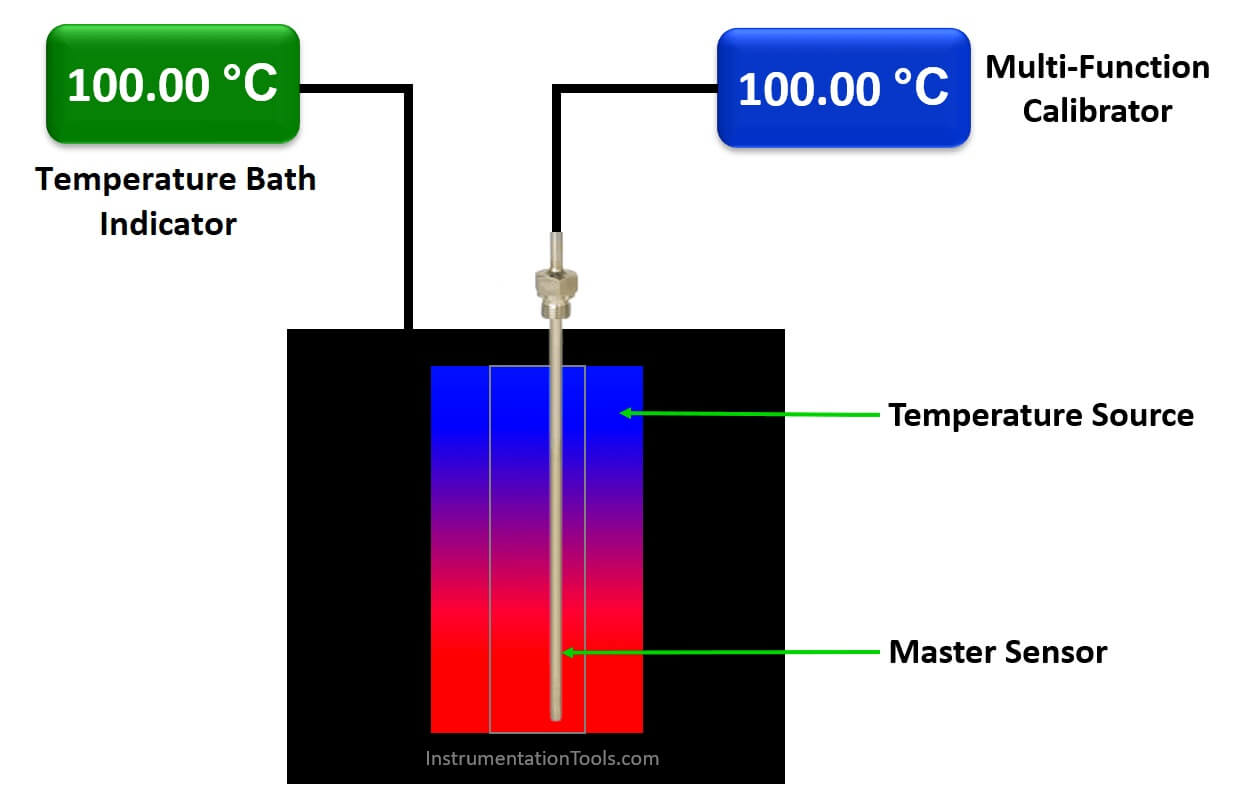
Insert the Master RTD Sensor/Thermocouple into the Temperature Bath (UUC) at Center Position of Temperature Bath.

Now connect a calibrated multi-function calibrator to this master sensor to read the sensor output in temperature units like degree C.

If you don’t have a multi-function calibrator then you can use calibrated Multimeter. Note down the output and do the conversion to temperature using RTD or thermocouple standard temperature tables.

Step 2:

Decide the calibration points of the UUC before starting the actual calibration.

For e.xample

  • The calibration points of the Oven are 50, 100,150, 200 degrees Celsius.
  • The Calibration points of the Refrigerator are 2, 5 10, 15 degrees Celsius.

Discuss Calibration points with the end-user and according to the working range of the instrument, calibration points are decided.

If you had an old calibration record file then you can find the respective calibration points details in it.

Step 3:

Set the first calibration point on Temperature Bath (UUC).

Allow temperature bath to attend the desired set temperature and Stabilize at first calibration point.

Step 4:

Note down the UUC temperature reading displayed on the indicator of Temperature Bath and Master RTD Sensor/Thermocouple reading.

The temperature Bath shows two readings, Set temperature, and Actual Temperature. Note down the Actual temperature reading.

Take 5 readings at a single different setpoint in intervals of 30 sec.

Calculate the average reading for each calibration point.

Step 5:

Repeat Step 3 and Step 4 for other calibration points.

i.e., do the same calibration step for 100, 150, and 200 degrees Celsius.

Record all the readings in your calibration sheet.

If you liked this article, then please subscribe to our YouTube Channel for Instrumentation, Electrical, PLC, and SCADA video tutorials.

You can also follow us on Facebook and Twitter to receive daily updates.

Read Next:

  • RTD Calibration Procedure
  • Selection of Master Instrument
  • Importance of Unit Measurement
  • Why Calibration is Important?
  • Calibration of Level Transmitter
Don't Miss Our Updates
Be the first to get exclusive content straight to your email.
We promise not to spam you. You can unsubscribe at any time.
Invalid email address
You've successfully subscribed !

Continue Reading

Different Types of Thermometers
Helix Bimetallic Thermometer Principle
RTD Testing Methods in Calibration Laboratory
Thermocouples Sources of Error
Calibration of Weight using the ABBA Method
Thermowell Outer Diameter Larger than Nozzle Inside Diameter?
Share This Article
Facebook Whatsapp Whatsapp LinkedIn Copy Link
Share
Leave a Comment

Leave a Reply Cancel reply

Your email address will not be published. Required fields are marked *

Stay Connected

128.3kFollowersLike
69.1kFollowersFollow
210kSubscribersSubscribe
38kFollowersFollow

Categories

Explore More

Thermocouple Software compensation
Spiral Bimetallic Thermometer Principle
Shunt Calibration of a Strain Gauge Load Cell
Stroke Checking Procedure for GCV, SRV, IGV, and LFBV
How a 4 Wire RTD Works ?
Temperature Switch Principle
How 3 Wire RTD Lead Wire Resistance Eliminated?
Hierarchy of Calibration Organizations

Keep Learning

Sample Raw DataSheet for Pressure Calibration

Sample Raw DataSheet for Pressure Calibration

RTD

Why 4 wire RTD Measurement Accuracy is better than 2 and 3 wire RTD?

Basic components of a Thermowell

What is Thermowell and How-to choose Thermowell Probe Length ?

Capacitance Level measurement principle

Capacitance Level Sensor Principle, Limitations, Installation & Calibration

Stability and Uniformity of Temperature Bath

Stability and Uniformity of Temperature Bath

The Control Valve Stroke Test Procedure

Control Valve Stroke Test Procedure

what is calibration

Important Terms in Calibration

Celsius and Fahrenheit Temperature Values

What Temperature are Celsius and Fahrenheit Value Same ?

Learn More

Dual Solenoid Valve on Control Valve

Why we Require Dual SOV on a Control Valve?

Turbine Meter in Gas Metering System

Read Gas Composition from Gas Metering System using RS485 Protocol

Power Electronics Objective Questions

IGBT Objective Questions

WirelessHART Network Protocol

WirelessHART Network Protocol

ControlLogix

Difference Between CompactLogix and ControlLogix

Wave Trap in Power Line carrier Communication

What is a Wave Trap? – Power Line Carrier Communication

Intrinsic Safety Barriers

Intrinsically Safe Barriers Questions and Answers

Digital Output Card With Relay and Wet Contact

Wiring Diagrams of PLC and DCS Systems – DI, DO, AI, AO

Menu

  • About
  • Privacy Policy
  • Copyright

Quick Links

  • Learn PLC
  • Helping Hand
  • Part Time Job

YouTube Subscribe

Follow US
All rights reserved. Reproduction in whole or in part without written permission is prohibited.
Welcome Back!

Sign in to your account

Username or Email Address
Password

Lost your password?