Write a PLC program where you can’t change the motor direction unless the stop push button is pressed first.
For instance, If the clockwise (CW) push button (PB) is pressed the motor runs in CW and if the counter-clockwise (CCW) push button is pressed the motor does not change its direction unless the stop push button is pressed first.
Note: the best practice to learn the PLC programming is to start writing the PLC program, take your time before you review the answer.
Inputs and Outputs:
I0.0: CW Push Button (Normally Open contact)
I0.1: CCW Push Button (Normally Open Contact)
I0.2: Stop Push Button (Normally Closed contact)
Q0.0: Motor CW
Q0.1: Motor CCW
Motor Stop Interlock for Changing the Direction
PLC Program description
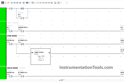
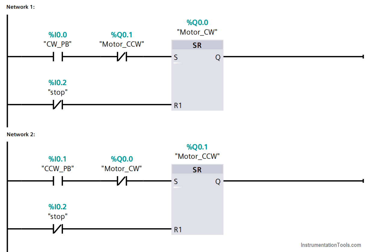
Network 1:
- When the CW PB is pressed and the Motor CCW is not running the set bit in the flip flop is energized.
- When the stop PB is pressed the reset bit in the flip flop is energized.
- If the CW PB is pressed while the Motor CCW is running the set bit would never be energized
Network 2:
- When the CCW PB is pressed and the Motor CW is not running the set bit in the flip flop is energized.
- When the stop PB is pressed the reset bit in the flip flop is energized.
- If the CCW PB is pressed while the Motor CW is running the set bit would never be energized.
Conclusion
There is an interlock between the two motor directions that it is not allowed to toggle between the two directions unless the motor is stopped.
Author: Karim Ali Anwar
If you liked this article, then please subscribe to our YouTube Channel for PLC and SCADA video tutorials.
You can also follow us on Facebook and Twitter to receive daily updates.
Read Next:
- Siemens SCADA Tags
- Motor Ladder Logic
- Statement List Program
- Connect a Solenoid Valve
- Flexible IO Modules