Inst ToolsInst ToolsInst Tools
  • Courses
  • Automation
    • PLC
    • Control System
    • Safety System
    • Communication
    • Fire & Gas System
  • Instrumentation
    • Design
    • Pressure
    • Temperature
    • Flow
    • Level
    • Vibration
    • Analyzer
    • Control Valve
    • Switch
    • Calibration
    • Erection & Commissioning
  • Interview
    • Instrumentation
    • Electrical
    • Electronics
    • Practical
  • Q&A
    • Instrumentation
    • Control System
    • Electrical
    • Electronics
    • Analog Electronics
    • Digital Electronics
    • Power Electronics
    • Microprocessor
  • Request
Search
  • Books
  • Software
  • Projects
  • Process
  • Tools
  • Basics
  • Formula
  • Power Plant
  • Root Cause Analysis
  • Electrical Basics
  • Animation
  • Standards
  • 4-20 mA Course
  • Siemens PLC Course
Reading: Two Electrode Conductivity Probes Principle
Share
Font ResizerAa
Inst ToolsInst Tools
Font ResizerAa
  • Courses
  • Design
  • PLC
  • Interview
  • Control System
Search
  • Courses
  • Automation
    • PLC
    • Control System
    • Safety System
    • Communication
    • Fire & Gas System
  • Instrumentation
    • Design
    • Pressure
    • Temperature
    • Flow
    • Level
    • Vibration
    • Analyzer
    • Control Valve
    • Switch
    • Calibration
    • Erection & Commissioning
  • Interview
    • Instrumentation
    • Electrical
    • Electronics
    • Practical
  • Q&A
    • Instrumentation
    • Control System
    • Electrical
    • Electronics
    • Analog Electronics
    • Digital Electronics
    • Power Electronics
    • Microprocessor
  • Request
Follow US
All rights reserved. Reproduction in whole or in part without written permission is prohibited.
Inst Tools > Blog > Analyzers > Two Electrode Conductivity Probes Principle

Two Electrode Conductivity Probes Principle

Last updated: February 12, 2018 8:29 am
Editorial Staff
Analyzers
No Comments
Share
5 Min Read
SHARE

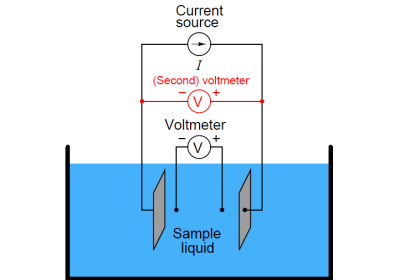
We may measure the electrical conductivity of a liquid solution by passing an electric current through it. The most primitive form of conductivity sensor (sometimes referred to as a conductivity cell ) consists of two metal electrodes inserted in the solution, connected to a circuit designed to measure conductance (G), the reciprocal of resistance ( 1/R):

Two Electrode Conductivity Probes

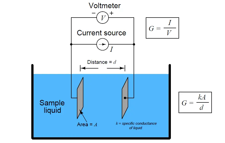
A general problem faced with electrical measurements of liquid conductance is that the derived conductance value (G) does not tell us much about the liquid itself, because that measurement depends just as much on the geometry of the plates (their area A and separation distance d) as it does on the ionic activity of the liquid solution. If we are trying to analyze the liquid all by itself, what we really need is a measurement of specific conductivity (k, or conductance) independent of plate geometry.

We face the same essential problem when trying to quantify the resistivity of metal conductors. If we measure the resistance of a piece of wire in the same manner shown in the previous illustration measuring liquid conductance, we arrive at a result that is every bit as much dependent on the length and area of the wire specimen as it is on the resistivity of the metal itself:

Conductivity Probes

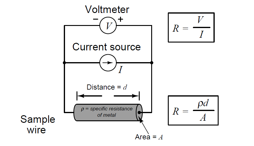
In other words, the calculated value in ohms (from direct voltage and current measurements) for the resistance of this metal specimen doesn’t tell us much about that type of metal in general, but rather it tells us the resistance of that particular specimen of wire. In order to calculate the specific resistance (ρ, or resistivity) of the metal, we must also account for the specimen’s length (d) and cross-sectional area (A).

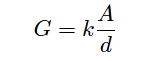
The mathematical relationship between conductance (G), plate area (A), plate distance (d), and the actual conductivity of the liquid (k) is expressed in the following formula:

Conductance

Where,
G = Conductance, in Siemens (S)
k = Specific conductance (conductivity) of liquid, in Siemens per centimeter (S/cm)
A = Electrode area (each), in square centimeters (cm2)
d = Electrode separation distance, in centimeters (cm)

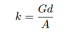
Manipulating this formula to solve for conductivity (k) of the liquid:

Conductance formula

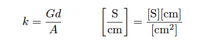
The unit of Siemens per centimeter for liquid conductivity may seem odd at first, but it is necessary to account for all the units present in the variables of the equation. A simple dimensional analysis proves this:

Conductance units

In order to quantity the plate geometry for any particular cell, manufacturers typically express the fraction d/A as a single value called the cell constant, symbolized by the Greek letter “theta” (θ) and expressed in the unit of inverse centimeters (cm−1):

Conductance units - 1

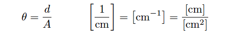
Substituting θ for the quotient d/A in the conductivity formula reveals conductivity to be the simple product of measured conductance (G) and the cell constant:

k = Gθ

Where,
k = Specific conductivity of liquid, in Siemens per centimeter (S/cm)
G = Conductance, in Siemens (S)
θ = Cell constant, in inverse centimeters (cm−1)

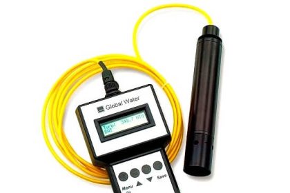
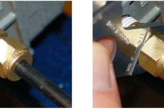
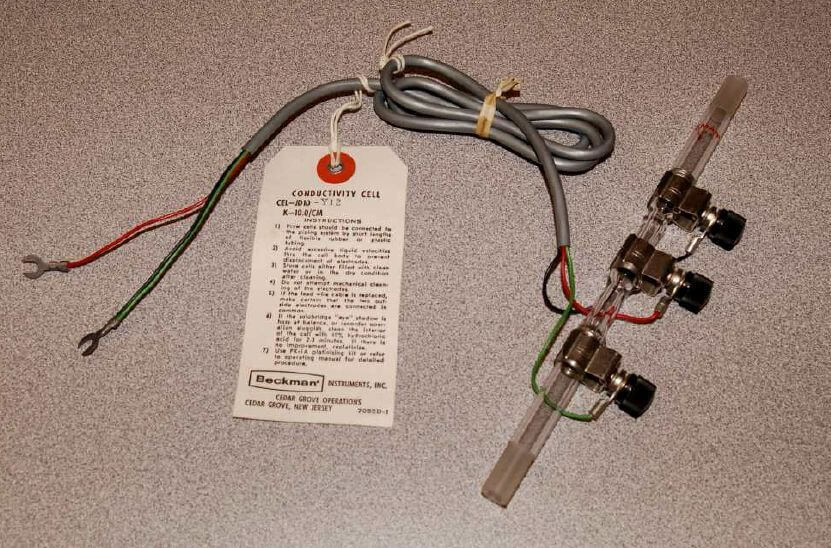
The following photograph shows an example of such a direct-contact style of conductivity probe, consisting of stainless steel electrodes contacting the fluid flowing through a glass tube:

Two Electrode Conductivity Probes Principle

Two-electrode conductivity cells are not very practical in real applications, because mineral and metal ions attracted to the electrodes tend to “foul” the electrodes over time forming solid, insulating barriers on the electrodes. While this “electroplating” action may be substantially reduced by using AC instead of DC to excite the sensing circuit, it is usually not enough. Over time, the conductive barriers formed by ions bonded to the electrode surfaces will create calibration errors by making the instrument “think” the liquid is less conductive than it actually is.

Also Read : Toroidal Conductivity Sensors Principle

Don't Miss Our Updates
Be the first to get exclusive content straight to your email.
We promise not to spam you. You can unsubscribe at any time.
Invalid email address
You've successfully subscribed !

Continue Reading

Gas Filter Correlation (GFC) Spectroscopy
Measuring Gases Concentration in Chromatograph
Ammonia Gas Detector Working Principle and Calibration
Basics of Chromatograph Operation
Infrared Non Dispersive CO2 Analyzer Working Principle
Technologies for Oxygen Gas Measurement
Share This Article
Facebook Whatsapp Whatsapp LinkedIn Copy Link
Share
Leave a Comment

Leave a Reply Cancel reply

Your email address will not be published. Required fields are marked *

Stay Connected

128.3kFollowersLike
69.1kFollowersFollow
210kSubscribersSubscribe
38kFollowersFollow

Categories

Explore More

Conductivity Transmitter Calibration Procedure
What is Cell Constant in Conductivity Analyzer? and its Importance
Luft detector Principle
Sox Nox Analyzer
Dew Point Meter Principle
NDIR Gas Analyser Working Principle
H & B Gas Analyzer Principle and Calibration Procedure
pH Analyzer Interview Questions and Answers

Keep Learning

Free chlorine Analyzer Principle

Free chlorine Analyzer Principle

Moisture and Dew Point Analyzer Problems

Moisture and Dew Point Analyzer Problems and Troubleshooting Tips

Ph Meter Principle

pH measurement

In-Situ Zirconia Oxygen Analyzer

Oxygen (O2) Measurement in Flue Gas

Dew Point Method Humidity Measurement

Humidity Measurement Principle

Single-beam non-dispersive analyzer

Single-beam Non-dispersive Analyzer

Scintillation Counter Theory

Scintillation Counter Principle

mass spectrometer sample system

Mass Spectrometer Working Principle

Learn More

Keyphasor Principle

What is Keyphasor ? How does Keyphasor works ?

PLC Program using Logic GATEs

PLC Logic GATE Program

3-way globe valve

What is Mixing or Diverting Valve ?

Fire Alarm System Commissioning Procedure

Fire Alarm System Commissioning Procedure

Steam Turbine Driven Centrifugal Compressors Leak due to Broken Instrument

Discharge Head 3‑monthly leaks of Steam Turbine Driven Centrifugal Compressors

Digital Electronics Multiple Choice Questions

Fast Adder & Serial Adder Multiple Choice Questions

Cable Schedule

What is Cable Schedule and Junction Box Schedule?

Pressure and Temperature Compensation for Flow Transmitter

Why Pressure & Temperature Compensation required for Orifice Flow Meters ?

Menu

  • About
  • Privacy Policy
  • Copyright

Quick Links

  • Learn PLC
  • Helping Hand
  • Part Time Job

YouTube Subscribe

Follow US
All rights reserved. Reproduction in whole or in part without written permission is prohibited.
Welcome Back!

Sign in to your account

Username or Email Address
Password

Lost your password?