Inst ToolsInst ToolsInst Tools
  • Courses
  • Automation
    • PLC
    • Control System
    • Safety System
    • Communication
    • Fire & Gas System
  • Instrumentation
    • Design
    • Pressure
    • Temperature
    • Flow
    • Level
    • Vibration
    • Analyzer
    • Control Valve
    • Switch
    • Calibration
    • Erection & Commissioning
  • Interview
    • Instrumentation
    • Electrical
    • Electronics
    • Practical
  • Q&A
    • Instrumentation
    • Control System
    • Electrical
    • Electronics
    • Analog Electronics
    • Digital Electronics
    • Power Electronics
    • Microprocessor
  • Request
Search
  • Books
  • Software
  • Projects
  • Process
  • Tools
  • Basics
  • Formula
  • Power Plant
  • Root Cause Analysis
  • Electrical Basics
  • Animation
  • Standards
  • 4-20 mA Course
  • Siemens PLC Course
Reading: Pulsed Fluorescence SO2, H2S, CS Analyzer Working Principle
Share
Notification Show More
Font ResizerAa
Inst ToolsInst Tools
Font ResizerAa
  • Courses
  • Design
  • PLC
  • Interview
  • Control System
Search
  • Courses
  • Automation
    • PLC
    • Control System
    • Safety System
    • Communication
    • Fire & Gas System
  • Instrumentation
    • Design
    • Pressure
    • Temperature
    • Flow
    • Level
    • Vibration
    • Analyzer
    • Control Valve
    • Switch
    • Calibration
    • Erection & Commissioning
  • Interview
    • Instrumentation
    • Electrical
    • Electronics
    • Practical
  • Q&A
    • Instrumentation
    • Control System
    • Electrical
    • Electronics
    • Analog Electronics
    • Digital Electronics
    • Power Electronics
    • Microprocessor
  • Request
Follow US
All rights reserved. Reproduction in whole or in part without written permission is prohibited.
Inst Tools > Blog > Analyzers > Pulsed Fluorescence SO2, H2S, CS Analyzer Working Principle

Pulsed Fluorescence SO2, H2S, CS Analyzer Working Principle

Last updated: May 27, 2018 6:46 am
Editorial Staff
Analyzers
7 Comments
Share
3 Min Read
SHARE

The Pulsed Fluorescence Analyzer operates on the principle that H2S can be converted to SO2. SO2 molecules absorb ultraviolet (UV) light and become excited at one wavelength, then decay to a lower energy state emitting UV light at a different wavelength. Specifically,

The sample is drawn into the analyzer through the SAMPLE bulkhead, as shown in Figure. From the bulkhead the sample is either shunted to a converter or bypasses the converter and is led straight through to a hydrocarbon kicker. When sample goes through the converter, the instrument response represents the combined sulphur (CS) reading, that is, the sum of SO2, H2S, and any residual reduced sulphur species. When bypassing the converter, the instrument reads SO2 only. The difference between the two signals is the inferred H2S reading.

Pulsed Fluorescence SO2-H2S-CS Analyzer Working Principle

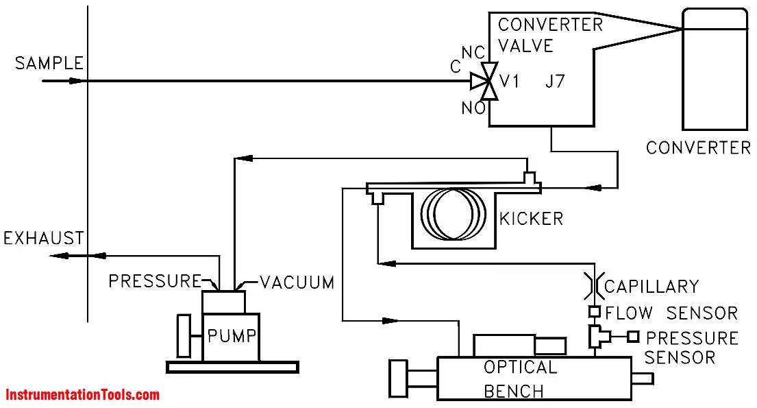
The sample, whether coming directly from the bulkhead or processed in the converter, then flows through a hydrocarbon kicker. The kicker removes hydrocarbons from the sample by forcing the hydrocarbon molecules to differentially permeate through the tube wall. The SO2 molecules pass through the hydrocarbon kicker unaffected.

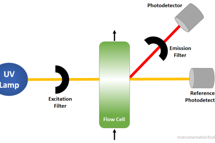
The sample then flows into the fluorescence chamber, where pulsating UV light excites the SO2 molecules. The condensing lens focuses the pulsating UV light into the mirror assembly. The mirror assembly contains four selective mirrors that reflect only the wavelengths which excite SO2 molecules.

As the excited SO2 molecules decay to lower energy states they emit UV light that is proportional to the SO2 concentration. The bandpass filter allows only the wavelengths emitted by the excited SO2 molecules to reach the photomultiplier tube (PMT). The PMT detects the UV light emission from the decaying SO2 molecules. The photodetector, located at the back of the fluorescence chamber, continuously monitors the pulsating UV light source and is connected to a circuit that compensates for fluctuations in the UV light.

As the sample leaves the optical chamber, it passes through a flow sensor, a capillary, and the shell side of the hydrocarbon kicker. The analyzer outputs the SO2, H2S, CS ranges concentration levels to the display.

Don't Miss Our Updates
Be the first to get exclusive content straight to your email.
We promise not to spam you. You can unsubscribe at any time.
Invalid email address
You've successfully subscribed !

Continue Reading

Is it Easy to Measure Natural Gas Flow and Volume?
Questions and Answers on Gas
Flame Ionization Detector (FID) Principle
Turbidity Analyzer Working Principle
pH Analyzer Calibration and Troubleshooting
Oxidation-Reduction Potential (ORP) Sensor Calibration Procedure
Share This Article
Facebook Whatsapp Whatsapp LinkedIn Copy Link
Share
7 Comments
  • Krishna chaitanya says:
    October 8, 2016 at 12:18 pm

    Please make a app for apple iPod and iPhone

    Reply
    • S Bharadwaj Reddy says:
      October 8, 2016 at 1:13 pm

      Noted/

      Reply
  • Niki Chan says:
    February 14, 2017 at 7:10 am

    Any supplier of Pulsed Fluorescence H2S Analyzer?

    Reply
  • Ladha Ramesh says:
    March 5, 2019 at 1:59 am

    What is the best wavelength for H2S, SO2, NH3, CO, CO2, NO measurement

    Reply
  • Ladha Ramesh says:
    March 5, 2019 at 2:00 am

    What is maximum wavelength of UV and IR

    Reply
    • Padma Tiwari says:
      April 11, 2020 at 12:18 pm

      For so2 4.67micrometer

      Reply
    • Padma Tiwari says:
      April 11, 2020 at 12:23 pm

      For co 4.67 micro meter
      For so2 214 nenometer

      Reply

Leave a Reply Cancel reply

Your email address will not be published. Required fields are marked *

Stay Connected

128.3kFollowersLike
69.1kFollowersFollow
210kSubscribersSubscribe
38kFollowersFollow

Categories

Explore More

Calibration and Troubleshooting of Oxygen Analyzer
Working Principle of Gas chromatograph
What is the Application of Electrical Conductivity Meter?
NDIR Analyzer Filter Cells
Automated Calibration
Conductivity Analyzer Common Problems and Troubleshooting Tips
Humidity Sensor Working Principle
Gas Analyzer Sampling System

Keep Learning

Ammonia Gas Detector Calibration

Ammonia Gas Detector Working Principle and Calibration

Measurement of Carbon Dioxide in Flue Gas

Measurement of Carbon Dioxide in Flue Gas

Dew Point Method Humidity Measurement

Humidity Measurement Principle

Oil in Water Analyzer Principle

Oil in Water Analyzer Working Principle

Luft detector

Luft detector Principle

conductivity transmitter

Conductivity Transmitter Calibration Procedure

TOC Analyzer Principle

Total Organic Carbon Analyzer Principle

Moisture and Dew Point Analyzer Problems

Moisture and Dew Point Analyzer Problems and Troubleshooting Tips

Learn More

PLC-based mail box automation

PLC Program for Mailbox with Letter Counting & Light Indicators

PLC Cooking Timer Example for Kitchen Automation

PLC Cooking Timer Example for Kitchen Automation

Safety Requirement Specifications (SRS) - Safety Instrumented System

Safety Requirement Specifications (SRS) – Safety Instrumented System

Objective Questions of Building Fire and Gas Detectors

Objective Questions of Building Fire and Gas Detectors

Density-Measurement-using-DP-Transmitter-for-open-tank

Density Measurement for Open Tank with Constant Level Application

Smart DP transmitter Formula

DP Transmitter Error Calculations

Capacitor Principle

Capacitor

p-type-semiconductor

N Type and P Type Semiconductors

Menu

  • About
  • Privacy Policy
  • Copyright

Quick Links

  • Learn PLC
  • Helping Hand
  • Part Time Job

YouTube Subscribe

Follow US
All rights reserved. Reproduction in whole or in part without written permission is prohibited.
Welcome Back!

Sign in to your account

Username or Email Address
Password

Lost your password?