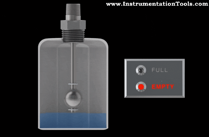
A change in fluid level can correspondingly cause the float to travel up or down. The float end fixed with a permanent magnet which we can see in the below figure. A reed switch is placed in horizontal to the float. On Level raises, the float moves near to the reed switch, the magnet makes the reed switch state change. This change in output contact is used to detect level signal.
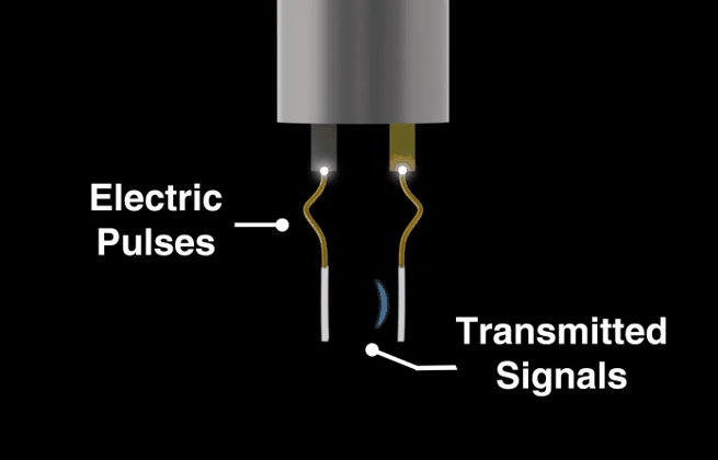
The reed switch relies on two basic scientific principles namely: buoyancy and magnetism. Buoyancy causes the float (which contains a magnet) to rise with the liquid and magnetism helps open and close the switch.
A change in liquid levels raises or lowers the float up or down. The end of the pivot arm (non float side) contains a permanent magnet that can repel the switch magnet (inside the stationary ‘stem’ of the entire structure).
When the float magnet moves close to the switch’s stationary stem, the float magnet repel the switch magnet which either opens or closes the Electrical circuit contact which is used to detect the level.
Also Read : Reed Switch Principle
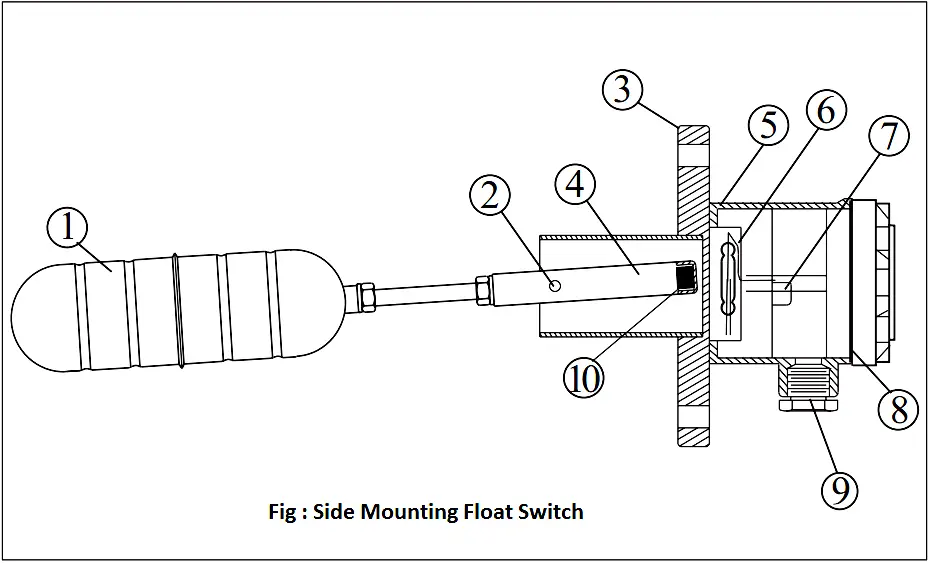
1. Float 2. Shaft 3. Flange 4. Pivot 5. Housing 6. Reed Switch 7. Terminal 8. O-ring 9. Conduit 10. Magnet 11. Screw 12. Microswitch Conduit/Connection
Typical Installation
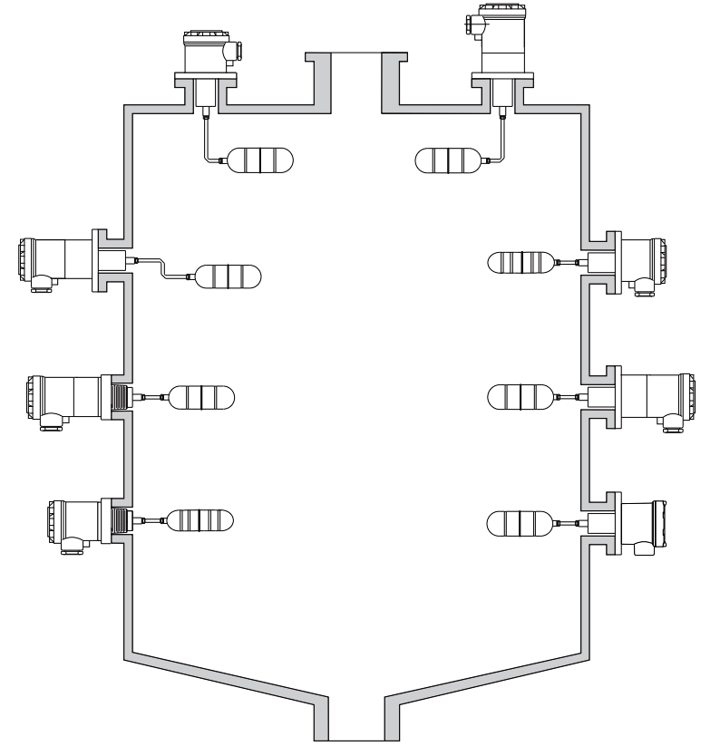
Source : FineTek