This article discusses LS Electric’s example PLC program for clothes washing systems using the XG5000 PLC software.
Clothes Washing System
This Clothes Washing System can only be started if the Mixing Process amount parameter has been set. There are Start and Stop buttons to Start and Stop the washing process.
This PLC system starts with the process of filling water into the Washing Tub for 20 seconds. Continuing with the Mixing Process, the Washing Tub will rotate Forward and Reverse at 5 second intervals.
Next, the clothes Drying Process will be carried out for 20 seconds, the Washing Tub will rotate at high speed to remove the water. The alarm indicator will be active when the entire process has been carried out.
Program Objective
This PLC program has 2 buttons:
- The START (P00000) button is used to turn ON the system.
- The STOP (P00001) button is used to turn OFF the system.
The system can only be started if the Mixing Process value in memory word SV_MIXING (D00000) has been set.
Water Filling Process
The water-filling process will Start when the START button (P00000) is Pressed. The WATER_IN (P00040) output will be ON for 20 seconds to fill water into the Washing Tub.
Mixing Process
The Mixing Process will be carried out after the water filling process is complete. The Washing Tub will rotate Forward and Reverse according to the Mixing Process value Set in the memory word SV_MIXING(D00000).
When turning Forward, the MIX_FORWARD (P00041) Output will be ON and when turning Reverse the MIX_REVERSE (P00042) Output will be ON.
The MIX_FORWARD (P00041) and MIX_REVERSE (P00042) Outputs will be ON (alternately) with a time interval of 5 seconds.
Drying Process
When the mixing process is complete, the drying process continues.
The DRYER (P00043) Output will be ON for 20 Seconds to rotate the Wash Tub at high speed.
Alarms
The alarm indicator will be Active to provide a warning that the washing process has been completed. The ALARM (P00044) Output will be ON after the drying process and the ALARM (P00044) output will be OFF if the STOP (P00001) button is Pressed.
LS Electric PLC Program Example
Inputs and Outputs Addressing
| Comment | Input (I) | Output (Q) | Memory Bits | Memory Word | Timers |
| START | P00000 | ||||
| STOP | P00001 | ||||
| WATER_IN | P00040 | ||||
| MIX_FORWARD | P00041 | ||||
| MIX_REVERSE | P00042 | ||||
| DRYER | P00043 | ||||
| ALARM | P00044 | ||||
| TIMER_WATER | T0000 | ||||
| TIMER_FORWARD | T0001 | ||||
| TIMER_REVERSE | T0002 | ||||
| TIMER_DRYER | T0003 | ||||
| MACHINE_ON | M00000 | ||||
| SV_MIXING | D00000 | ||||
| PV_FORWARD | D00001 | ||||
| PV_REVERSE | D00002 |
PLC Program Explained
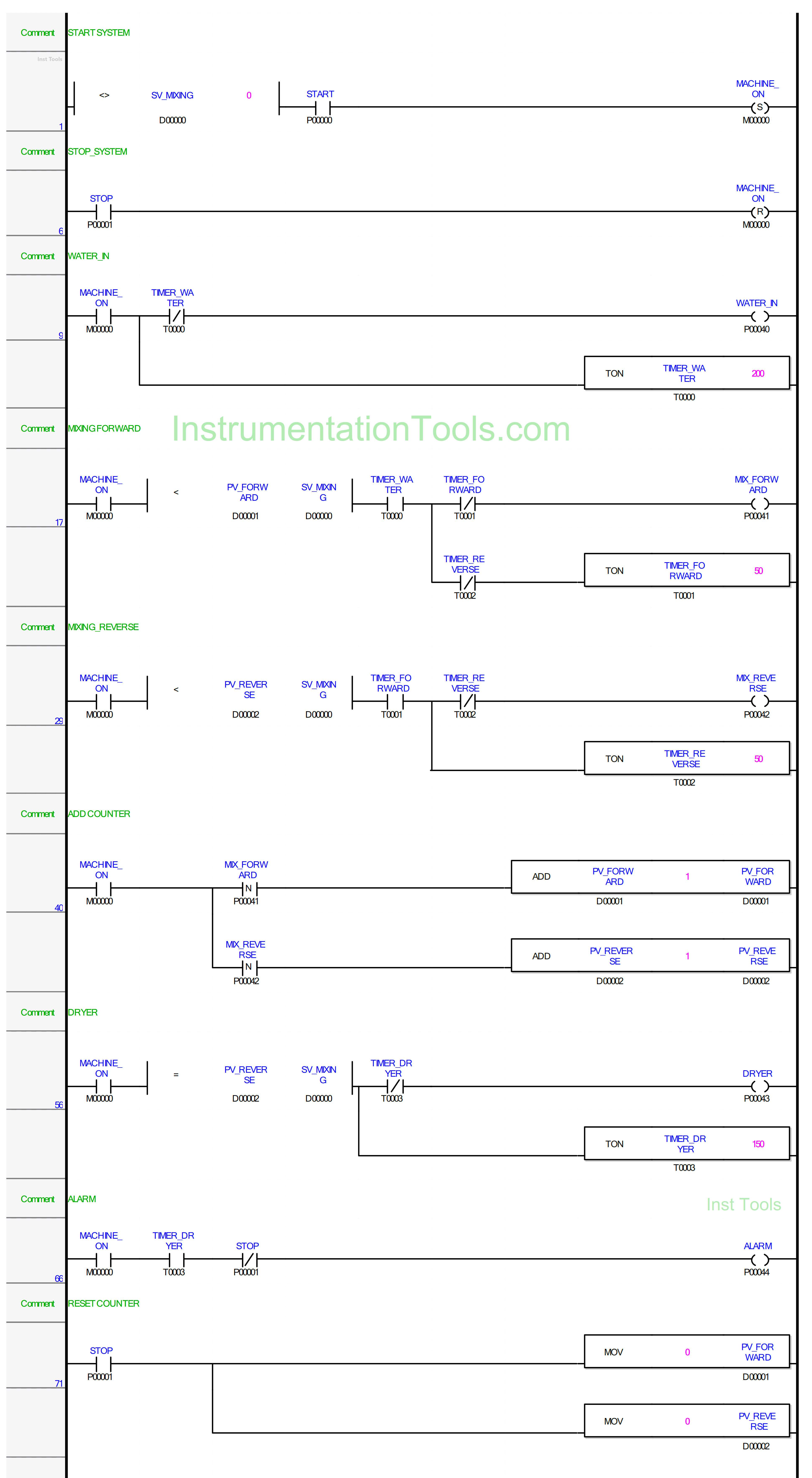
RUNG 1 (START SYSTEM)
In this Rung, the memory bit MACHINE_ON (M00000) changes to the HIGH state if the value in memory word SV_MIXING (D00000) is not equal to zero “0” and the START (P00000) button is Pressed. Because it uses the SET Coil Instruction, the memory bit MACHINE_ON (M00000) will remain in the HIGH state even though the START (P00000) button has been Released.
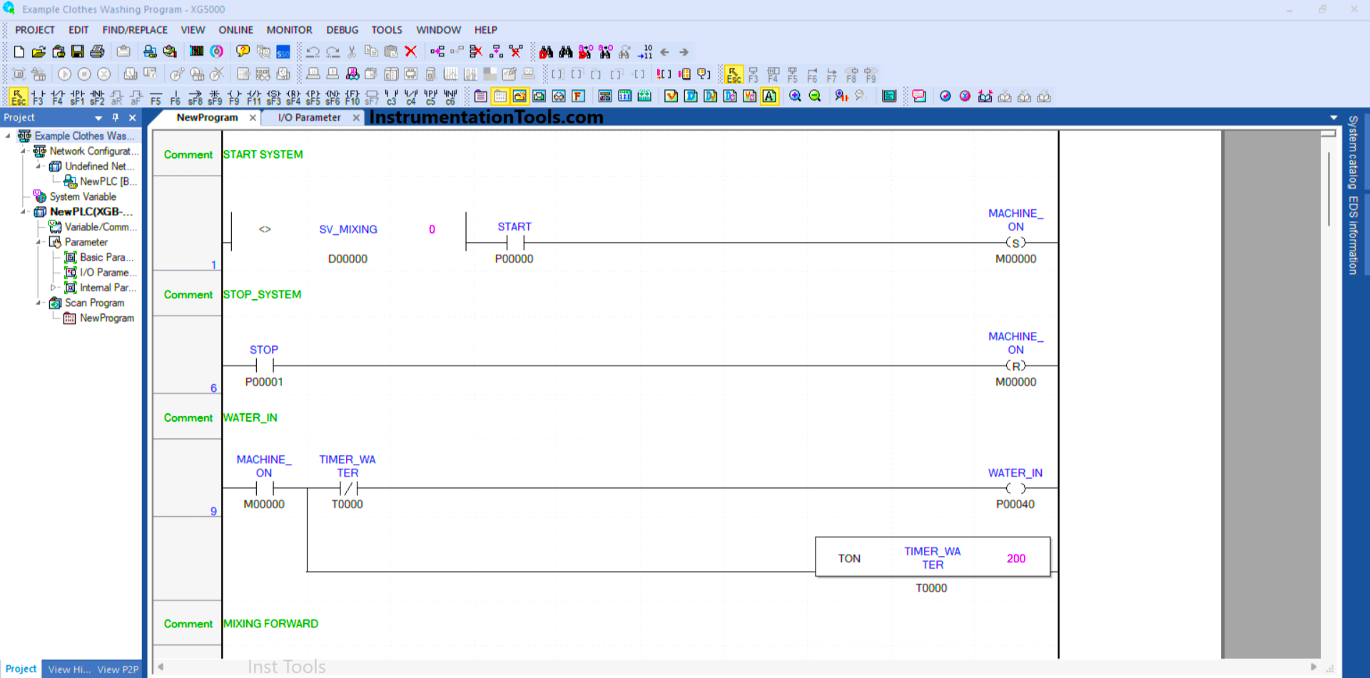
RUNG 6 (STOP_SYSTEM)
Because it uses the RESET Coil Instruction, the memory bit MACHINE_ON (M00000) will go into a LOW state if the STOP (P00001) button is Pressed.
RUNG 9 (WATER_IN)
When the NO contact of the memory bit MACHINE_ON (M00000) is in the HIGH state, the WATER_IN (P00040) output will be ON.
Timer TIMER_WATER (T0000) Starts counting up to 20 seconds, and when Timer TIMER_WATER (T0000) finishes counting Output WATER_IN (P00040) will be OFF due to Interlock.
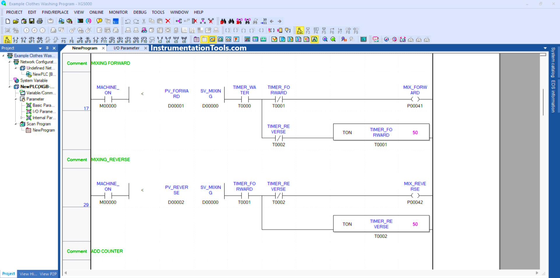
RUNG 17 (MIXING FORWARD)
In this Rung, when the NO contacts of memory bits MACHINE_ON (M00000) and TIMER_WATER (T0000) are in the HIGH state and the value in memory word PV_FORWARD (D00001) is Less Than SV_MIXING (D00000), then the Output MIX_FORWARD (P00041) will be ON and the Timer TIMER_FORWARD (T0001) will count up to 5 seconds.
The MIX_FORWARD (P00041) output will be OFF when the TIMER_FORWARD (T0001) Timer has finished counting.
When the NC contact of TIMER_REVERSE (T0002) is in the HIGH state, the TIMER_FORWARD (T0001) Timer will be OFF.
RUNG 29 (MIXING_REVERSE)
In this Rung, when the NO contact of memory bit MACHINE_ON (M00000) and the Timer TIMER_FORWARD (T0001) are in the HIGH state and the value in memory word PV_REVERSE (D00002) is Less Than SV_MIXING (D00000), then the Output MIX_REVERSE (P00042) will be ON and the Timer TIMER_REVERSE (T0002) will count up to 5 seconds.
When the TIMER_REVERSE (T0002) timer has finished counting, the MIX_REVERSE (P00042) output will be OFF.
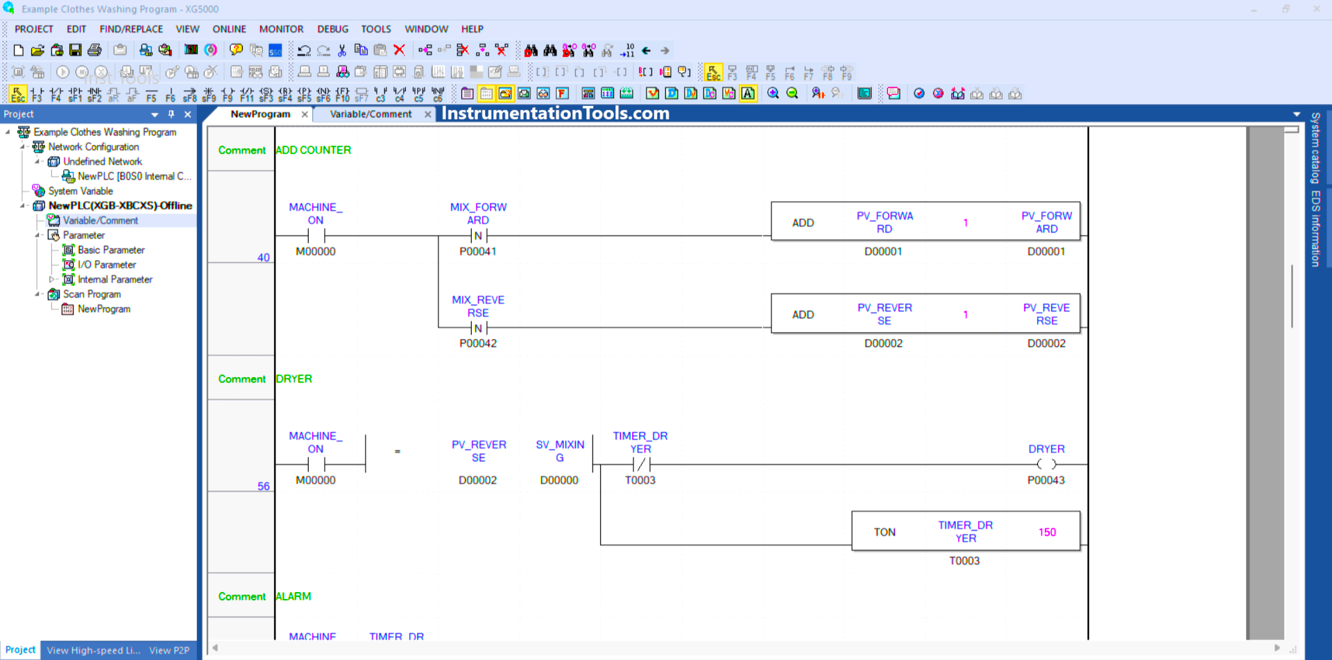
RUNG 40 (ADD COUNTER)
In this Rung, when the NO contact of memory bit MACHINE_ON (M00000) and Output MIX_FORWARD (P00041) in the HIGH state, the value in memory word PV_FORWARD (D00001) will increase (+1) because it uses the ADD Instruction.
Or if the output MIX_REVERSE (P00042) is in the HIGH state, then the value in memory word PV_REVERSE (D00002) will increase (+1) because it uses the ADD instruction.
RUNG 56 (DRYER)
In this Rung, when the NO contact of memory bit MACHINE_ON (M00000) in the HIGH state and the value in memory word PV_REVERSE (D00002) is Equal To SV_MIXING (D00000), then the Output DRYER (P00043) will be ON. The TIMER_DRYER (T0003) timer will count up to 15 seconds.
The DRYER (P00043) output will be OFF when the TIMER_DRYER (T0003) Timer has finished counting.
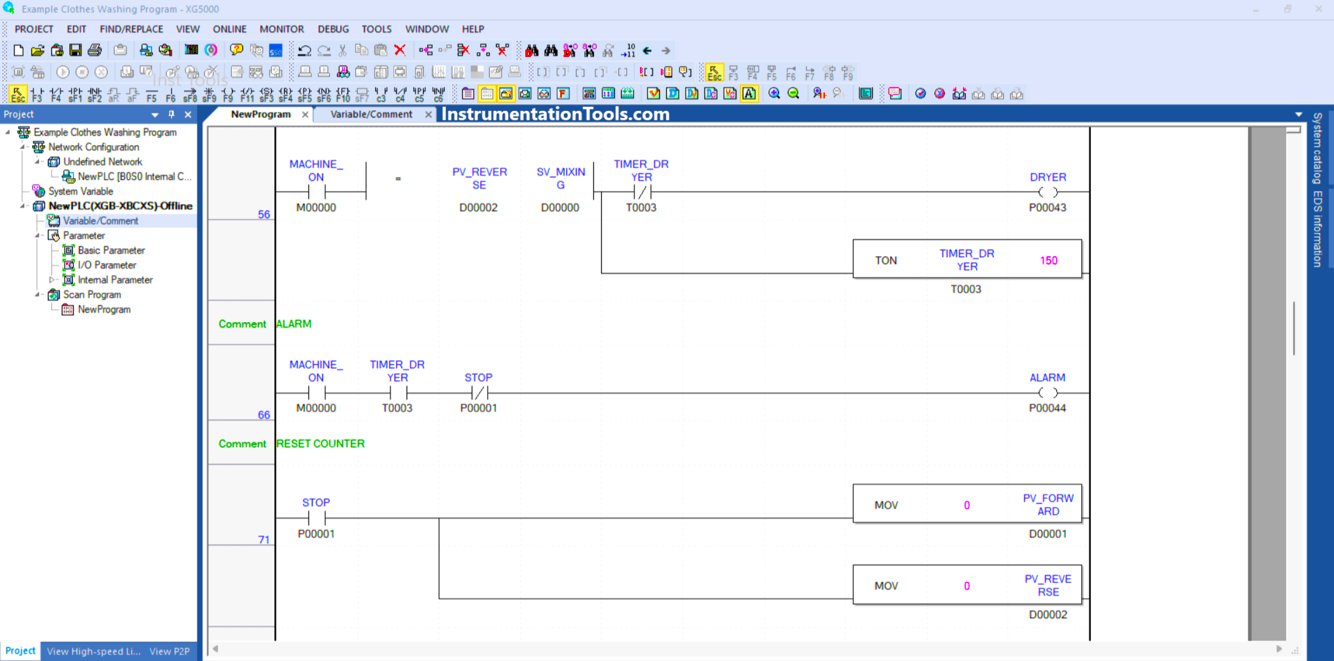
RUNG 66 (ALARM)
If the NO contacts of the memory bits MACHINE_ON (M00000) and TIMER_DRYER (T0003) are in the HIGH state, then the ALARM Output (P00044) will be ON.
When the STOP button (P00001) is Pressed, the ALARM output (P00044) will be OFF.
RUNG 71 (RESET COUNTER)
In this Rung, when the STOP (P00001) button is Pressed, the memory words PV_FORWARD (D00001) and PV_REVERSE (D00002) will become zero value “0”.
The MOV instruction moves the zero value “0” to the memory words PV_FORWARD (D00001) and PV_REVERSE (D00002).
Read Next:
- Automatic Railway Crossing Gate Logic
- Bread Oven Control Auto Mode Logic
- PLC Programming 3 Motors with Priority
- PLC Crane Movement Control Program
- Conveyor PLC Sorting with Color Detection