In this article, you will learn the PLC programming example on multiple LEDs using the Set Coil instruction.
Note: The PLC program example was created for learning practices for the engineers and technicians.
PLC Program using Set Coil
Problem Statement
Design a PLC ladder logic for the following application.
If Switch 1 is ON, then LED I and LED II will be ON.
If Switch 1 is OFF, then LED I and LED II will be still ON.
If Switch 2 is ON, then LED III and LED IV will be ON.
If Switch 2 is OFF, then LED III and LED IV will be still ON.
PLC Learning Video
This video helps you to learn this PLC program example from scratch. It is helpful for beginners.
PLC I/O List
Digital Inputs:
The DI signals are listed below.
- Switch 1: I0.0
- Switch 2: I0.1
Digital Outputs:
The DO signals are listed below.
- LED 1: Q0.0
- LED 2: Q0.1
- LED 3: Q0.2
- LED 4: Q0.3
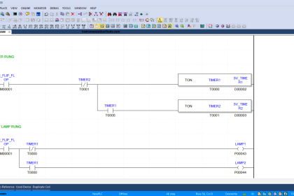
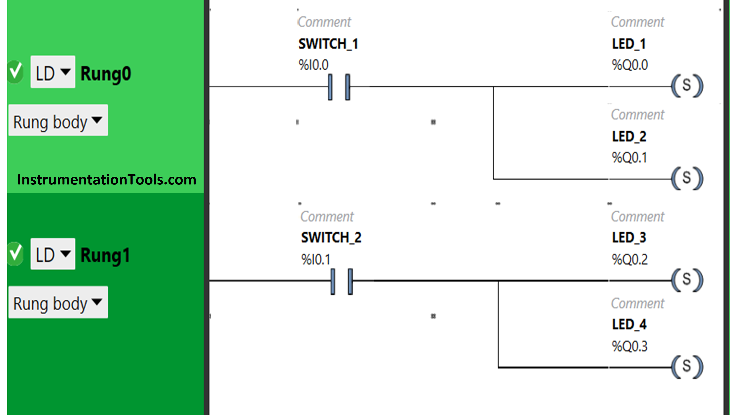
Ladder Diagram
Logic Explanation
In this PLC example, we used EcoStruxure Machine Expert Basic PLC software for programming.
In the above PLC program, we have used Normally Open Contact for Switch 1 (I0.0), Switch 2 (I0.1).
We have also used Set coils for the outputs LED 1 (Q0.0), LED 2 (Q0.1), LED 3 (Q0.2) and LED 4 (Q0.3).
Switch 1 is connected to two LEDs i.e., LED 1 and LED 2.
LED 3 and LED 4 are connected to the input, Switch 2.
For LED 1 and LED 2 to turn ON, input Switch 1 should be turned ON.
LED 1 and LED 2 will remain ON when the input Switch is turned OFF.
When Switch 2 is turned ON, then LED 3 and LED 4 will turn ON.
Then, when switch 2 is turned OFF, LED 3 and LED 4 will remain ON.
Result
When Switch 1 is ON
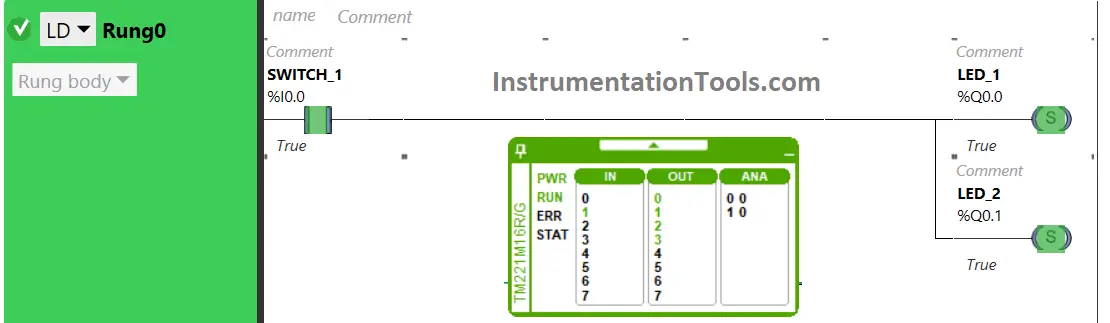
As Switch 1 is used as Normally Open Contact, it will allow the signal to flow through it. As a result, LED 1 and LED 2 will turn ON.
When Switch 1 is OFF
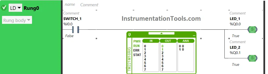
There is use of Set Coils for LED 1 and LED 2. So, the outputs will not turn OFF when input Switch 1 is turned OFF. LED 1 and LED 2 will remain ON.
When Switch 2 is ON
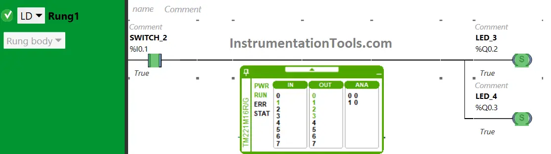
LED 1 and LED 2 will turn ON when the input Switch 2 is turned ON. The input Switch 2 is taken as Normally Open Contact, it will allow signal to the outputs.
When Switch 2 is OFF
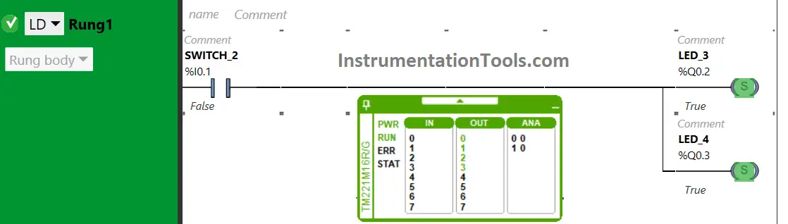
The outputs, LED 3 and LED 4 will not turn OFF when input Switch 1 is turned OFF. We have used Set coils for the outputs.
On turning OFF the input will not turn OFF the Outputs. Therefore, when Switch 2 is turned OFF, Led 3 and Led 4 will remain ON.
If you liked this article, then please subscribe to our YouTube Channel for PLC and SCADA video tutorials.
You can also follow us on Facebook and Twitter to receive daily updates.
Read Next:
- Electrical Diagram into PLC Program
- How to Get a PLC Programmer Job?
- Seven Segment Display Working Principle
- PLC Programming Example with Switches
- Faceplates in FactoryTalk View Studio