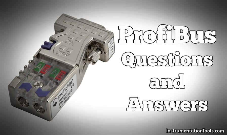
ProfiBus Questions and Answers
What happens if the PROFIBUS cable has a short-circuit?
A short-circuit at the PROFIBUS cable can disturb a data communication in the particular segment.
The devices in that area will NOT get damaged! The short-circuit can easily be detected with an oscilloscope and even the distance to the problem can be masured.
If the end-user wants to keep the installation running during a short-circuit, he can pick the following solutions:
- Install a redundant system.
- Divide the installation in multiple parallel segments coupled by repeaters, OLMs or ProfiHubs and ComBricks.
- Install the cable in separate cable trays.
In which standard(s) is PROFIBUS specified?
The PROFIBUS communication is specified in IEC 61158 Type 3 and IEC 61784.
IEC 61158 Type 3 includes the entire range of PROFIBUS, consisting of the versions DP-V0, DP-V1 and DP-V2.
IEC 61784 specifies the properties of the Communication Profile Family CPF 3 which is PROFIBUS.
What is the cost comparison between conventional and PROFIBUS cabling?
It is a common fact that PROFIBUS reduces cable costs a lot, but there is a more that comes with it:
- Reduction of cable trays
- Energy savings
- Less documentation
- Better overview
- Reduction of test time
- Less spare parts
- Easy to expand or change
- Shorter downtimes because of quick repair
- Easy to dismantle
This is only infrastructure and the initial savings. But the real money making starts with the maintenance and the operational costs.
PROFIBUS is an excellent choice, but some training is required to get awareness about the advantages.
Also Read : Foundation Fieldbus Electrical Parameters
Give some basic tips for installing a PROFIBUS DP network?
- Always use PROFIBUS cable and connectors.
- Do not exceed 32 devices per segment (including repeaters, OLMs and couplers).
- Make sure the segment length is in contrast with the baudrate.
- Make sure every segment has powered termination on both ends.
- Avoid spur lines.
- Avoid swapping the wires (A=green, B=red).
- Mark how long the cables really are and update the drawings.
After installation you should test your work:
- Are the addresses correctly set?
- No short circuit or break in the cable?
- Can you communicate with the devices?
Why are termination problems the most common fault?
A lot of people are aware that termination has to be powered and activated at both ends of the cable. 4
What they do not know, is that it has to be activated again when you are using repeaters, OLMs or Profihubs.
Every segment has to be terminated! This often slips in when people are using lots of fiber optic and there is only a short length of copper cable in the cabinets. Even this short cable has to be terminated at both ends.
Which tools do you need for troubleshooting a running PROFIBUS installation?
There are 2 basic tools which are absolutely necessary! You need a bus analyzer to verify the protocol quality and an oscilloscope to verify the signal quality.
With these tools combined you can find 99 % of all errors. ProfiTrace 2 is a Combi-Analyzer that has both tools integrated.
The multi-meter is NOT usable for signal analysis! It will only be used to check a connection between 2 points.
What is SINEC L2-DP? Is this different than PROFIBUS DP?
SINEC L2-DP is PROFIBUS DP! Siemens did at one time use their own names for product designation.
However, since this proved to be confusing (with L2 in the name), the L2 part of the designation was dropped in favour of just DP to avoid confusion.
Another example: SINEC S1 is AS-i.
Is PROFIBUS a single or multi-protocol technology?
Within PROFIBUS there is only one communication layer implemented which is;
PROFIBUS DP. Based on this communication layer, several device profiles are defined in the application layer. These profiles provide common data, diagnostics and parameters for the end-user.
Sometimes people are confused with PROFIBUS DP and PA, but the only difference is the physical interface.
In fact, a PROFIBUS PA device is a PROFIBUS DP device with an application profile suited for the process industry.
Can PROFIBUS meet the requirements for fast communication speed and does it have a longer message length compared to other buses?
- PROFIBUS can run on 12 Mbps, which makes it the fastest fieldbus in the world.
- The messages have only 9 bytes overhead which makes it very efficient.
- An installation with 30 devices can have a cycle time of less than 1 ms.
- PROFIBUS is the choice for fast message delivery in the industrial automation environments.
What makes PROFIBUS unique in terms of Cycle time, Real-Time behavior and Diagnostics?
- PROFIBUS and PROFINET have the fastest cycle time, which can be less than 1 ms.
- This cycle time is extremely stable which makes it Real-Time.
- For diagnostics we have standardized formats and maintenance tools that match perfectly with the demands that maintenance personal has.
Also Read : WirelessHART device Configuration
What are the benefits of PROFIBUS for the end-users compared to other systems?
First of all PROFIBUS is the only fieldbus that can be used in all parts of the factory (upstream, process and downstream).
This means you can use 1 type of control system, 1 knowledge package, 1 group of spare parts and 1 design strategy.
PROFBUS also has a very large number of manufacturers offering products and services. This means for almost every application there is solution and enough backup products available.
These products also have strengths in certain application areas such as; motion control or process control.
PROFIBUS guarantees that every product always works with products from other manufacturers.
It has Competence Centers that support the end-users with their automation questions and last but not least, Certified Training Centers provide training.
People from the working groups are working close together to create a better world considering the cost aspect and the environment. They have a special band! Different people from different companies can work together without political, business and personal barriers.
All faces pointing to the same direction and we get the job done! The result of their hard work is that; PROFIBUS and PROFINET can save you energy, weight, materials, spare parts, documentation and a lot of effort.
Is there an open source implementation of PROFIBUS available?
PROFIBUS is an open specification. Every company is allowed to create a master/slave implementation.
Some patents are relevant to the PROFIBUS DP specification. The patent holders have granted free of charge licenses to all members of any RPA. Non-members have to agree on a license with the patent holders.
If a company wants to release a PROFIBUS implementation (software or hardware) as an open-source solution, the rules are relevant that are agreed at the OSADL (Open Source Development Lab, see www.osadl.org).
These rules say that no implementation can be released as an open-source solution if it is covered by patents. This means that neither a PROFIBUS DP slave nor master can be registered as an open source implementation.
ProfiBus DP Questions and Answers
Will the choice of addresses influence the cycle time?
NO, the master will always cyclically communicate with the slaves, so for the cycle time it doesn? it matter what addresses they have.
What is the meaning of the acronym ‘GSD’ file?
GSD files contain information about the basic capabilities of a device. All devices are shipped with a GSD file, or a file can be downloaded from this web site or the vendor’s own web site.
With a GSD file, system integrators can determine basic data such as the communications options and the available diagnostics.
There are lots of interpretations concerning the acronym GSD, but the correct version is; ‘General Station Description’.
Can you explain the diagnostic message structure of DP-V0 devices?
DP-V0 slave devices require a 6 bytes long mandatory diagnostic part. It contains information about the connection/device status and during certification has to be exactly behaving according the standard.
Additionally to the mandatory diagnostic part, devices can also provide a device specific part with a maximum length of 244 bytes (including the 6 mandatory bytes and headers).
The device specific part can be defined by the device manufacturer (device related diagnostics) and/or a scheme of the standard can be implemented (identifier related and channel related diagnostics).
99% of the device manufacturers implement only the device related diagnostics.
It is highly recommended to specify the diagnostic data in the GSD file and manual of the device.
Most DP masters and diagnostic tools can extract the diagnostic information and make it available for the application software.
What is Tid2 in the busparameter settings?
This busparameter defines the delay the sender of an unacknowledged telegram shall wait until it may send another telegram. Tid2 is the maximum value of 2 variables:
- MaxTSDR
- TQUI + 2*TSET + 2 + TSYN
In most cases MaxTSDR has the highest value (Tid2 = MaxTSDR).
A typical message that uses Tid2 is the Global Control broadcast with PROFIBUS DP.
How many DP slaves can be configured in a network?
Most people say 126, but this is NOT true! The total number of DP slaves that can be put in data-exchange is 124, because of the master that uses an address and the reserved addresses 0 and 126 (these are blocked by the configuration tool).
Be careful:
- Address 2 could also be blocked for slaves
- The master itself can have a limit
Can we control the outputs of 1 slave with 2 masters (PLCs)?
NO, only 1 PLC has the right to control the outputs (safety feature).
The 2nd PLC can only READ the inputs/outputs.
What is the most commonly used transmission speed?
1.5 Mbps is the most commonly used transmission speed. This is the default speed when you create a new project. Most users don’t know what it is and keep this value.
Our experience is that most installation are running on a speed that is much too high for the application. When the speed is lower you can have longer cables and less chance of disturbances.
Reliable settings to make PROFIBUS DP communication more reliable?
YES, in the bus parameters of the master you can change some settings to make the communication more reliable:
- Retries/Repeats = 5
- Tqui = 9
- MinTSDR = 22
Is it necessary to reconfigure the bits & bytes in the control system when a new device is added to PROFIBUS?
When a PROFIBUS device is added in the control system configuration, the device gets new memory space assigned, which does NOT conflict with the existing configuration.
The existing configuration and program does not need to be touched. This makes PROFIBUS perfect for instrument expansion or complete machine copying.
Also Read : Foundation Fieldbus Standard Function Blocks
How is the term “plug and play” used in PROFIBUS ?
It has a double meaning; if you replace a device with the same type it works directly, because the configuration is stored in the control system.
Also, you can easily integrate a new device in your configuration by importing a GSD file and synchronizing the address of the device.
By serving standardized and profile based device descriptions PROFIBUS also enables a manufacturer independent device replacement.
Does PROFIBUS DP have self triggered alarms/diagnostics?
When a device has diagnostics it indicates this during the data exchange.
The master will immediately fetch the diagnostics and makes the information available for the end-user. The diagnostics from devices are completely event triggered.
Diagnostics are important for smooth and reliable operation. Devices report their own device status and indicate when they need service.
This reduces maintenance costs and can increase time between scheduled field visits.
Can we install PROFIBUS DP cable in a PA network?
Lots of users have the impression this will never cause a problem because of the high speed signal characteristics of DP cable (even if the impedance is not correct), but there are other factors that could make it very unstable
- There will be too much voltage loss at the end of the cable because of the higher loop resistance of standard DP cable (110 Ohm/km). PA cable has a loop resistance of 44 Ohm/km. When it is an Ex coupler with only 12.xV output, there is a change the last devices “get lost” all the time”.
- The DP cable gets over-powered because of its “thin” 0.64 mm diameter wires. PA cable wires have a diameter between 0.8 to 1.5 mm.
- PA Coupling components cannot handle the “thin” wires of the DP cable.
- When it is an Ex installation, the DP cable is probably not blue and not suitable for the FISCO Ex specs.
use only cable that complies with the PA specifications!
What is the minimum distance between 2 devices on PROFIBUS DP?
When the transmission speed is 1,5 Mbps or higher, it is highly recommended to have at least 1 m of cable between 2 devices.
The input capacitance of both devices will be compensated by the cable in order to preserve the common impedance.
When the devices would be very close together, there is a big chance the input capacitance causes reflections in the data communication (small short circuits).
The effect is much less at transmission speeds lower than 1.5 Mbps.
Does PROFIBUS DP cable always have a violet colour?
NO, because of certain application, protection and isolation classes, PROFIBUS DP cable can have another colour.
Example: ground cable and shipboard cable are black, robust cable is green. The standard cable is always violet!
Which pins on the DB9 connector are for communication?
- Pin 3 = B line (red wire)
- Pin 8 = A line (green wire)
The metal casing of the connector is used for the shielding.
Can 2 Profibus cables be installed inside the same metal conduit?
Yes, multiple (parallel) Profibus cables can be installed in a metal conduit.
It gives good behaviour when EMC is involved.
Why is there only 1 terminating resistor in an RS 485-IS plug?
The PROFIBUS DP – RS 485-IS standard (for Ex environments) has defined that the pull-up and pull-down resistors have to integrated in the devices.
This way they are always charged and can never cause a problem when somebody is moving the termination switch on a plug and it is more difficult to make a direct short circuit on the connector pins of the device (explosion protection). The resistor values are also different: 510 – 200 – 510.
It looks very confusing compared to regular PROFIBUS DP where the plugs contain 3 resistors. But it is correct!
ProfiBus PA Questions and Answers
I read in the PROFIBUS PA specifications that the max length of EACH spur is 30/60/120 m, but with PROFIBUS DP we have defined the spur length parameter as TOTAL spur length. Can you explain?
Because the baudrate is relatively low with PROFIBUS PA, spur lines are allowed to be long without disturbing the data communication and we can assign a fixed maximum length per spur / per device.
With PROFIBUS DP it is a different story; the high baudrate limits the spur line length. If we would fix the maximum length per device, it would only be 20 cm per spur for 32 devices and that would not make sense.
To solve this we define it as a total sum of all spurs together so that the end-user has more flexibility, because not all devices require a spur line.
What is FDE current with PROFIBUS PA devices (Fault Disconnection Electronics)?
Some PROFIBUS PA devices consume additional current when there is a problem internally or with its I/O.
FDE is this additional static/basic current consumption and has to be written in the manual of the device.
Some devices have no FDE current and always consume the regular current. When the problem intensifies, the device shuts itself down from the bus (no more power consumption).
Can we use EDD and/or DTM on any DP-V1 class 2 master?
NO, each tool uses its own technology:
- PDM: Modified EDD (based on PNO EDD, but not 100% compliant with PNO EDD)
- FieldCare: FDT/DTM technology
- PactWare: FDT/DTM technology
- CommuWin: Executable DLL’s (non standard solution)
A PA device has at least 3 function blocks. What are these blocks and what is their purpose?
In the process industry it is common to use blocks to describe the characteristics and functions of a measuring/manipulation point and to represent an application through a combination of these blocks.
The specification of PA devices uses this function block model to present functional sequences.
Physical Block (PB)
Describes the necessary parameters and functions of the device itself (e.g. software version, serial number, vendor ID, factory reset command).
There is only one Physical block in a PA device.
Transducer Block (TB)
Contains parameters which have effect or describe the type of sensor or actuator.
Transducer blocks may also contain parameters for calibration and linearization.
The processed information is passed on to the Function Block. If a device has more sensors, it has corresponding Transducer Blocks for every sensor.
Function Block (FB)
Contains one or more cyclically accessible inputs or outputs parameters (process values). These can be of analog or discrete nature. Other parameters: setup scaling, alarms and unit factorization.
Also Read : How Profibus Communication Works ?
What is a Profile within PROFIBUS PA?
Modern PA devices are intelligent and can execute part of the information processing in automation systems. This was previously done by the PLCs or DCS systems.
The PA profile is designed with co-operation of the process industry and defines all functions and parameters for different classes of instruments.
It is based on internationally accepted function block technology.
The profile contains descriptions for the following instrument types:
- Pressure (and differential)
- Level, temperature and flow
- Analog/digital inputs and outputs
- Valves and actuators
- Analyzers
The profile is divided into 2 classes (A and B):
Class A of the profile describes common parameters of simple devices.
The scope is limited to the basic functions. This set consists of the process variables (e.g. temperature, pressure, level) added by measured value state, the tag name and the engineering unit.
Class B is an extension to class A and will cover more complex application functions for identification, commissioning, maintenance and diagnosis.
The relationship of the parameters to the classes is visible within the parameter definitions and in the conformance statements.
To conclude: The PA profile defines cyclical data + status, diagnostic information and parameters. The PA profile assures interoperability and device exchangeability
What is a Profile Ident Number?
In cases where the device of manufacturer-A should be replaceable by an equivalent device of manufacturer-B, the standard Ident Number is no longer sufficient because a GSD file is associated with this number.
When the device is replaced a change in the configuration is necessary which will lead to a DCS/PLC stop. Therefore the PNO has assigned number ranges to dedicated device types (Profile Ident Numbers) in combination with certain Profile GSD files.
A device can support multiple Ident Numbers which are set by a parameterization tool. The end-user has to decide whether to select the Manufacturer specific Ident Number or the Profile Ident Number.
Examples:
- Transmitter 0x9700 to 0x970F
- Actuator 0x9710 to 0x971F
- Discrete input 0x9720 to 0x972F
- Discrete output 0x9730 to 0x973F
How can you measure the length of a PA segment?
This is almost impossible. Because of junction boxes, spur lines and the input resistance of the devices it is very hard to do. At the moment there is no tool available.
Why is termination important?
- Termination prevents reflections that can disturb the data communication.
- The higher the baudrate and the longer the cable, the more important termination becomes.
- Termination to be placed at both ends of every bus segment.
- With PROFIBUS DP, the termination is powered to provide an idle level when nobody is sending data.
- With PROFIBUS PA, the termination is a combination of a resistor and a capacitor.
Should there be distance between PROFIBUS and power cables?
- YES, even PROFIBUS can get disturbed by interference caused by parallel high voltage power lines.
- Always try to have at least 10 cm air space between the cables (depends on the level of the voltage).
- Most users mix all cables in one cable tray and that often leads to unreliable behaviour.
- Cables that cross each other will not cause problems. Creating distance is not the only requirement.
- Correct shielding is also a must!
Source : procentec

