In this system a loop controller receives a process variable signal from a 2-wire (loop-powered) transmitter, and sends its own 4-20 mA control signal to operate a control valve.
A data acquisition unit (DAQ) performs the auxiliary function of monitoring the process variable signal (voltage dropped across the loop resistor) and reporting it over a digital network where it is recorded on the hard drive of a personal computer. If it helps, you may think of a DAQ as being nothing more than a multi-channel voltmeter, sensing voltage between each of its input terminals (In 1, In 2) and its “common” (Com) terminal:
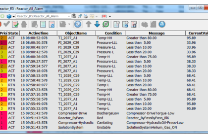
Loop Controller HART Signal Noise

Unfortunately, the DAQ not only registers the DC signal value, but also any HART pulses present in the transmitter circuit whenever a technician connects a HART communicator to the transmitter to do any maintenance work. The operators are annoyed by the misleading “noise” on the DAQ-recorded signal whenever a technician does routine work on that transmitter, and so they come to you asking for a solution.
Devise a simple modification to this circuit that will eliminiate (or at least minimize) the “HART noise” seen by the DAQ without impeding its ability to record normal process variable signal values.
Solution:
A simple resistor-capacitor low-pass filter connected between the resistor and the DAQ channel will suffice:

The values of R and C should be chosen to create a cutoff frequency lower than the lowest frequency expected with HART (1200 Hz), but not so low that relevant changes in the process variable would be excessively damped.
Beware of any solutions that would shunt HART signals around the 250 ohm loop resistance, such as a capacitor connected in parallel with DAQ input! This would solve the HART interference problem, but at the cost of impeding all HART communication!
Share your opinion on this topic with us through comments.
Credits: Tony R. Kuphaldt
Read Next:
- Configure HART Transmitter
- HART Communication Problems
- 4-20 mA Transmitter Voltage drop
- Sensor Trim in HART
- DCS System Layout
- 250 ohms Resistor for HART