Learn how to use latching and unlatching in PLC programming through example problems in this educational blog.
Note: This beginner-friendly PLC problem statement introduces ladder logic to students and helps them understand the latch and unlatch.
Latching and Unlatching in PLC
Problem Statement
Design a PLC ladder logic for the following application.
We are using two toggle switches to control four motors.
If Switch 1 is ON, then Motor I and Motor II will be ON.
If Switch 1 is OFF, then Motor I will be OFF and Motor II will be ON.
If Switch 2 is ON, then Motor II will be OFF and Motor III will be ON.
If Switch 2 is OFF, then Motor III will be OFF and Motor IV will be ON.
Ladder Logic Video

Inputs
The PLC program inputs are listed below.
Switch 1: I0.0
Switch 2: I0.1
Outputs
The PLC program outputs are listed below.
Motor 1: Q0.0
Motor 2: Q0.1
Motor 3: Q0.2
Motor 4: Q0.3
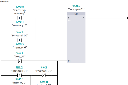
Latch and Unlatch Example PLC Logic
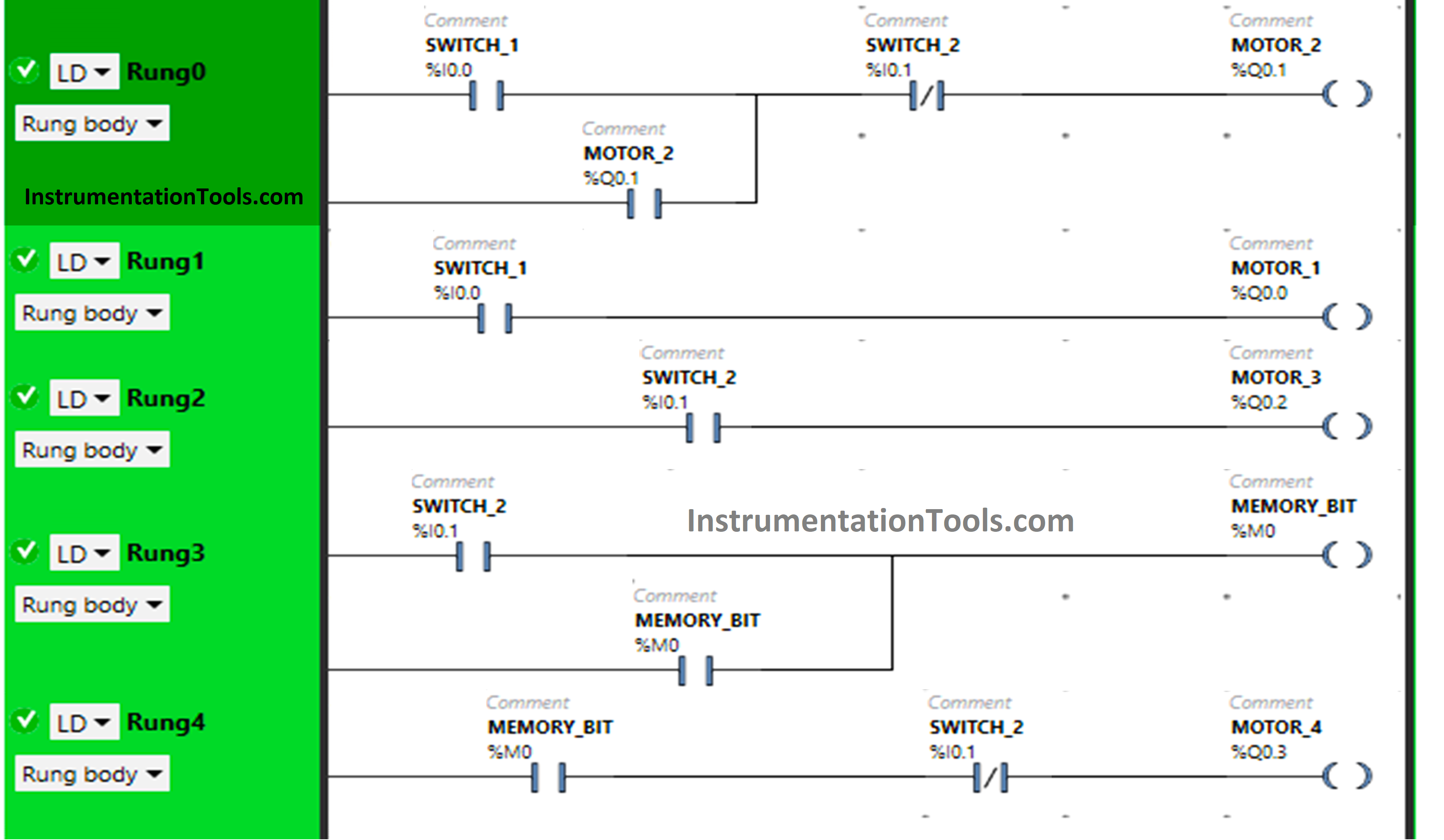
Program Explanation
In this example, we used EcoStruxure Machine Expert Basic v1.2 software for programming.
In the above program, we have used Normally Open Contacts as well as Normally Closed Contacts and Memory Bits.
Normally Closed Contact is used for Switch 2 in Rung0 and Rung4.
Motor 1 and Memory bit M0 are latched in Rung0 and Rung3 respectively.
For Motor 1 and Motor 2 to be ON, switch 1 should be ON.
Turning OFF switch 1 will turn OFF Motor 1 but Motor 2 remains ON.
When Switch 2 is turned ON, Motor 2 will turn OFF but Motor 4 will turn ON.
Program Simulation
Here we will show you the PLC program simulation results with different input statuses.
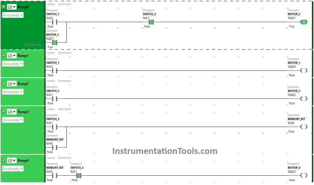
When Switch 1 is ON
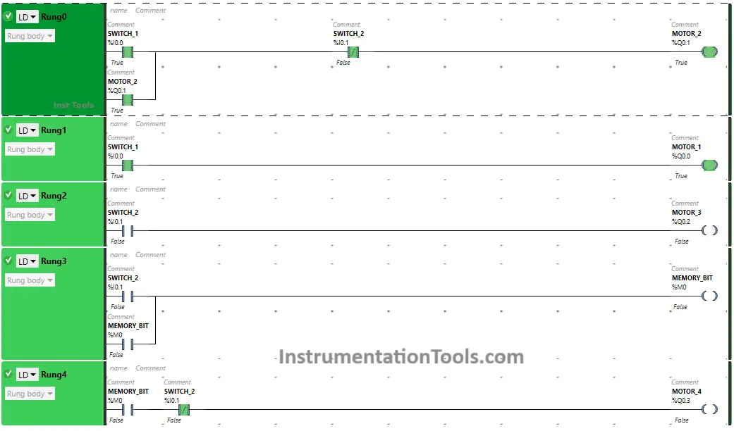
In Rung 0, the signal flows through switch 1, when in true state and Motor 2 will turn ON.
Motor 2 will also turn ON as switch 1 is directly connected with the output in Rung1.
When Switch 1 is OFF
When Switch 1 is turned OFF, Motor 1 will TURN OFF. The switch 1 is only Normally Open Contact connected with output Motor 1. But Motor II will remain ON.
The output Motor 2 is latched in Rung 0 and as a result, turning OFF the switch 1 will not turn OFF the motor 2.
When Switch 2 is ON
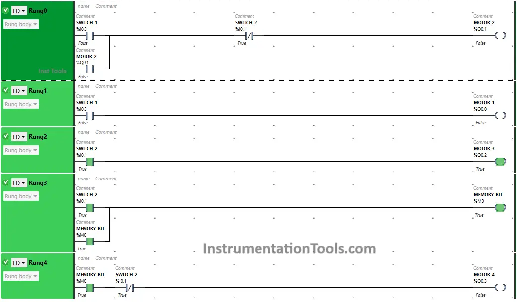
Turning ON Switch 2 will TURN OFF Motor 2. In Rung0, switch 2 is used as Normally Closed Contact which does not allow signal to pass. As a result, Motor 2 will turn OFF.
Also, in Rung 2 and Rung 3, turning ON Switch 2 will turn ON Motor 3 and memory bit M0 become true respectively.
When Switch 2 is OFF
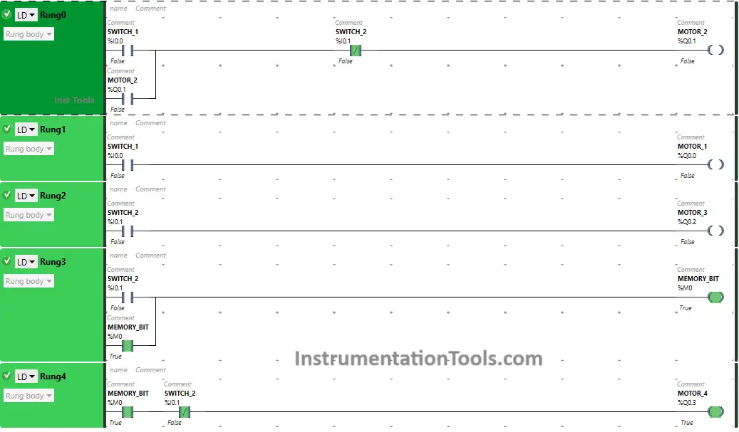
In Rung2, turning OFF switch 2 will turn OFF Motor 3. As Memory Bit M0 is latched in Rung3, when Switch 2 is turned OFF, the Memory Bit M0 will remain true.
In Rung 4, memory bit M0 is already true, and switch 2 as Normally Closed contact, in a false state, will allow the signal to pass through it. As a result, Motor 4 will turn ON.
If you liked this article, please subscribe to our YouTube Channel for PLC and SCADA video tutorials.
You can also follow us on Facebook and Twitter to receive daily updates.
Read Next:
- Schneider PLC Programming Example
- PLC Ladder Diagram for Latching Concept
- PLC Example on Multiple LEDs using Set Coil
- Solenoid Operated Valves and Latching Valves
- Password Protect HMI in Siemens TIA Portal?