Inst ToolsInst ToolsInst Tools
  • Courses
  • Automation
    • PLC
    • Control System
    • Safety System
    • Communication
    • Fire & Gas System
  • Instrumentation
    • Design
    • Pressure
    • Temperature
    • Flow
    • Level
    • Vibration
    • Analyzer
    • Control Valve
    • Switch
    • Calibration
    • Erection & Commissioning
  • Interview
    • Instrumentation
    • Electrical
    • Electronics
    • Practical
  • Q&A
    • Instrumentation
    • Control System
    • Electrical
    • Electronics
    • Analog Electronics
    • Digital Electronics
    • Power Electronics
    • Microprocessor
  • Request
Search
  • Books
  • Software
  • Projects
  • Process
  • Tools
  • Basics
  • Formula
  • Power Plant
  • Root Cause Analysis
  • Electrical Basics
  • Animation
  • Standards
  • 4-20 mA Course
  • Siemens PLC Course
Reading: Introducing PLC Programming using LogixPro Simulator Software
Share
Notification Show More
Font ResizerAa
Inst ToolsInst Tools
Font ResizerAa
  • Courses
  • Design
  • PLC
  • Interview
  • Control System
Search
  • Courses
  • Automation
    • PLC
    • Control System
    • Safety System
    • Communication
    • Fire & Gas System
  • Instrumentation
    • Design
    • Pressure
    • Temperature
    • Flow
    • Level
    • Vibration
    • Analyzer
    • Control Valve
    • Switch
    • Calibration
    • Erection & Commissioning
  • Interview
    • Instrumentation
    • Electrical
    • Electronics
    • Practical
  • Q&A
    • Instrumentation
    • Control System
    • Electrical
    • Electronics
    • Analog Electronics
    • Digital Electronics
    • Power Electronics
    • Microprocessor
  • Request
Follow US
All rights reserved. Reproduction in whole or in part without written permission is prohibited.
Inst Tools > Blog > PLC Tutorials > Introducing PLC Programming using LogixPro Simulator Software

Introducing PLC Programming using LogixPro Simulator Software

Introducing PLC programming practices using LogixPro simulator software and downloading procedure in detail.

Last updated: November 21, 2022 4:07 pm
Hussien Ghareb
PLC Tutorials
No Comments
Share
4 Min Read
SHARE

Introducing PLC programming practices using LogixPro simulator software and downloading procedure in detail.

Contents
Introduction to LogixProPLC Software OverviewEditing and Downloading in LogixProTroubleshooting & Debugging the ProgramAvailable Data Types for LogixPro Software

Building a programming mindset is not that simple, practicing and executing many programming ideas will help you.

However, preparing ready-made Coding Structures into your programming mindset using different techniques will strengthen your PLC programming ability much more and make the programming easier for you.

Today and for the next posts, we will learn a group of sharp, precise, and smart programming techniques, by a commonly used programming software LogixPro.

Introduction to LogixPro

The LogixPro simulator is an interactive educational tool, developed to assist students in the acquisition of the programming skills commonly used in the PLC control of process equipment and systems.

Download PLC Software: LogixPro Simulator

The significant advantage of this software is that it is widely available, you can download and install it without any restrictions.

PLC Software Overview

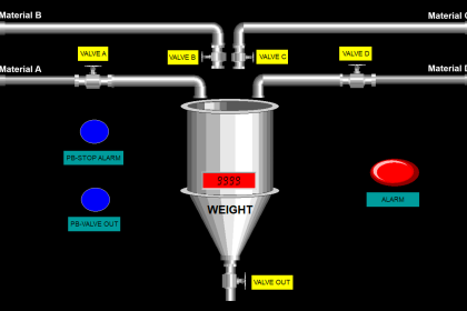
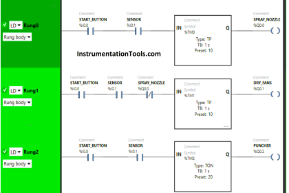
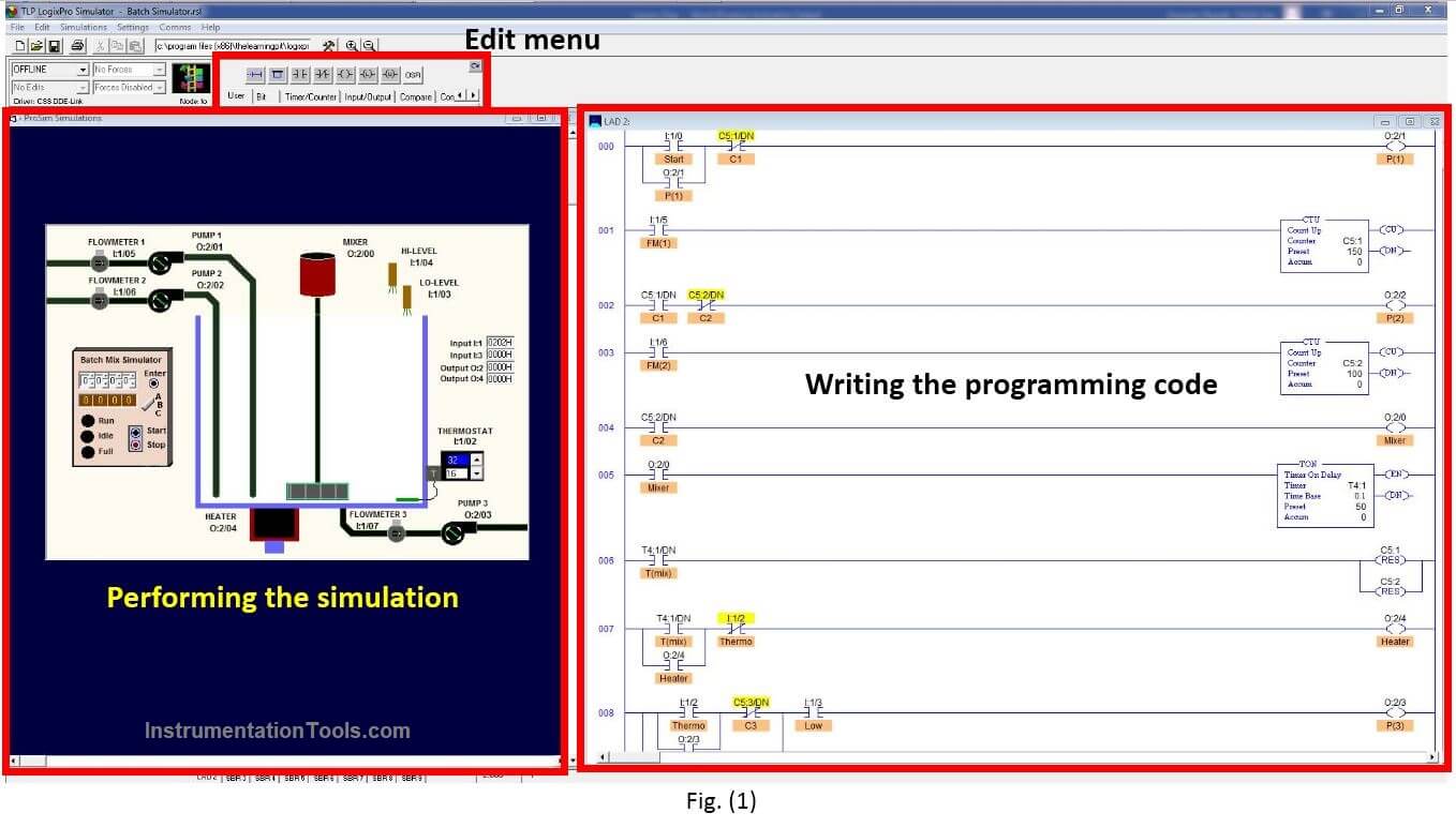
Here as shown in Fig. (1) we can see the three major components of the software:

  • Programming window
  • Simulator
  • Edit menu
LogixPro Simulator Software

Editing and Downloading in LogixPro

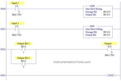
The Edit Panel provides easy access to all the RS Logix instructions and they may be simply dragged and dropped into your program.

Once your program is ready for testing, clicking on the “Toggle Button” of the Edit Panel as shown in Fig. (2) will bring the PLC Panel into view.

PLC Editing and Downloading in LogixPro

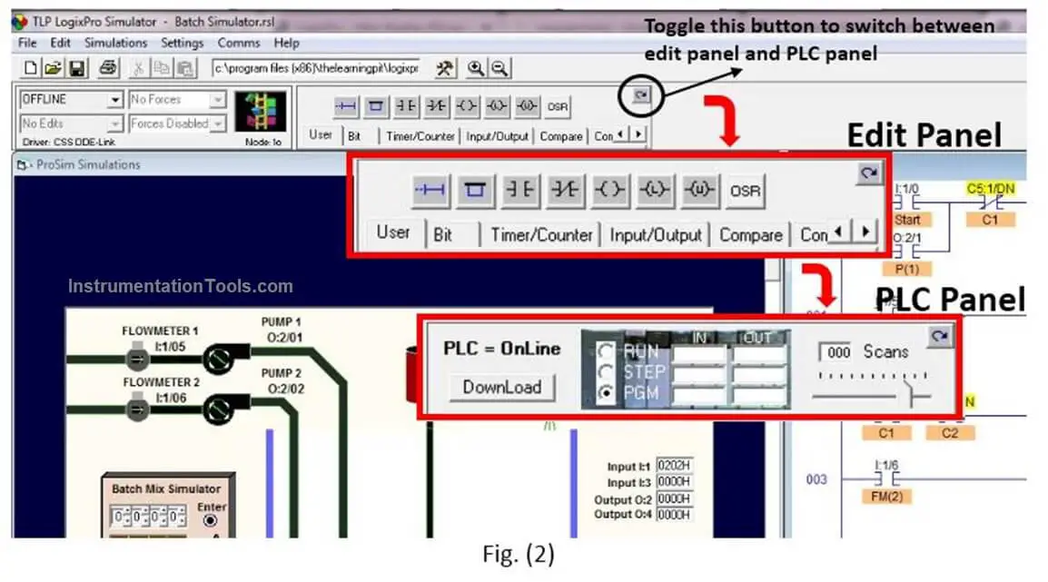
From the PLC Panel, you can download your program to the “PLC” and then place it into the “RUN” mode.

This will initiate the scanning of your program and the I/O of your chosen simulation.

Troubleshooting & Debugging the Program

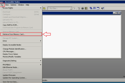
If you take a look at the PLC Panel, you’ll notice an adjustable Speed Control shown in Fig. (3).

This is not a component of normal PLCs but is provided with LogixPro so that you may adjust the speed of the simulations to suit your particular computer.

PLC Troubleshooting & Debugging the Program

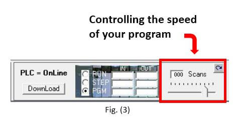
When the simulation is slowed, so is the PLC scanning. You can use this to good effect when trying to debug your program.

Set the scan slow enough and you can easily monitor how your program’s instructions are responding. This capability may not be typical of real PLCs, but for Training Purposes, you will find that it is an invaluable debugging tool.

Available Data Types for LogixPro Software

One of the best advantages of this software is the “Drag & Drop” property.

As you can see in Fig. (4) by clicking on the data table button a new window will pop up with all the available addresses that you will need.

Available Data Types for LogixPro Software

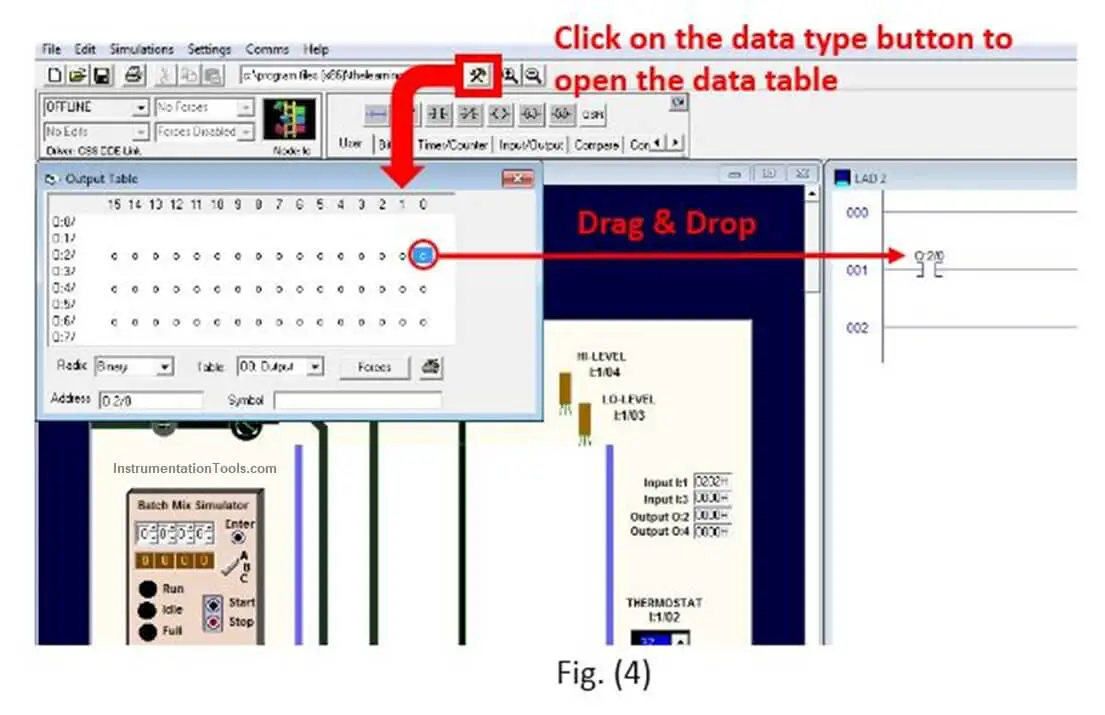
(Output, Input, Timers, Counters, Markers are signed with “B” …)

All you need to do is to choose the required data type then select the desired bit from the table then drag it and drop it to the specified location.

If you liked this article, then please subscribe to our YouTube Channel for Instrumentation, Electrical, PLC, and SCADA video tutorials.

You can also follow us on Facebook and Twitter to receive daily updates.

Read Next:

  • Function of Racks in PLC
  • Motor Classic Control Circuits
  • Control System Cyber Security
  • Features of Scada in IoT System
  • Conveyor Operation with a PLC
Don't Miss Our Updates
Be the first to get exclusive content straight to your email.
We promise not to spam you. You can unsubscribe at any time.
Invalid email address
You've successfully subscribed !

Continue Reading

How to Convert Voltage to Current using Resistor ?
PLC Scan Time
PLC Programming Best Practices and Tips
Communication between InTouch Scada and Allen Bradley PLC
Difference between PLC and Computers
Converter Instruction in Siemens PLC Programming
Share This Article
Facebook Whatsapp Whatsapp LinkedIn Copy Link
Share
Leave a Comment

Leave a Reply Cancel reply

Your email address will not be published. Required fields are marked *

Stay Connected

128.3kFollowersLike
69.1kFollowersFollow
210kSubscribersSubscribe
38kFollowersFollow

Categories

Explore More

How to Choose the Right Industrial Automation Solution?
Drive Multiple Speeds with Different Reference using PLC
What are High-Speed Inputs in PLC?
PLC Automatic Door Control System – Programming Example
What Factors Affect the Choice of PLC Programming Software?
Attendance System PLC Program using CX-Programmer
Complex Car Parking Logic in XG5000 LS Electric PLC
PLC Ladder Logic Example based on Set Coil and Reset Coil

Keep Learning

PLC based Automatic Packaging System

PLC based Automatic Packaging System

Database in Siemens PLC

Steps to Configure TCP/IP Communication in Siemens S7-1200 PLC

Switch NO or NC Contact

Normally-open and Normally-closed Switch Contacts

What is a Floating License - Automation Software Systems

What is a Floating License? – Automation Software Systems

Automatic Bottle Filling System using PLC

Automatic Bottle Filling System using PLC

PLC based Auto Manual Operation of Roll down Shutters

PLC based Auto/Manual Operation of Roll down Shutters in Industry

Top Non-PLC Certification Courses for Automation Professionals

Top Non-PLC Certification Courses for Automation Professionals

Industrial Automation and Control Systems (IACS)

Industrial Automation and Control Systems (IACS)

Learn More

Digital Electronics Multiple Choice Questions

Memory Devices Objective Questions – Part 2

Top US Universities that Offer Online Education

Top US Universities that Offer Online Education

Voltage Control Methods at Distribution System

Voltage Control Methods at Distribution System

Function Block Diagram - Studio 5000 Logix Designer

Define the Order of Execution in Functional Block Diagram of Studio 5000

calibration potentiometer for simulating the millivoltage output

Temperature Standards

Power MOSFET Safe Operating Area

Power MOSFET Safe Operating Area

Classic Control Circuits

Motor Classic Control Circuits using Single Push button

Digital Electronics Multiple Choice Questions

Parity Generators Objective Questions

Menu

  • About
  • Privacy Policy
  • Copyright

Quick Links

  • Learn PLC
  • Helping Hand
  • Part Time Job

YouTube Subscribe

Follow US
All rights reserved. Reproduction in whole or in part without written permission is prohibited.
Welcome Back!

Sign in to your account

Username or Email Address
Password

Lost your password?