Analog I/O is generally handled internally to the PLC as register values. For most PLCs the values can be mathematically manipulated using software math operations.
PLC Potential Problems
For more powerful PLCs, these can be done in binary, octal, decimal or hexadecimal arithmetic.
However, in the lower cost PLCs, the PLC may be limited in the number systems it is capable of handling, so designer may be forced to work in a number system other then decimal.
When this occurs, simple conversions between the PLC’s number system and decimal will allow the designer to verify input values and program output values.
Example Problem
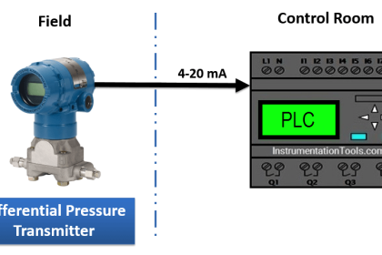
A voltage of 3.500 volts is applied to an 8-bit 5 volt unipolar analog input of a PLC. Using monitor software, the PLC analog input register shows a value of 2638. Is the analog input working correctly?
Solution
First, convert 2638 to decimal. It would be 2 x 82 + 6 x 81 + 3 x 80 = 179. For an 8-bit
5 volt unipolar converter, 179 would correspond to 179 x 5 / 28 = 3.496 volts.
Since the resolution is 5 / 28 = 0.0195 volts, the result is within ½ of a bit and is therefore correct.
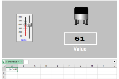
Analog I/O Problems
After installing an analog input system, it sometimes becomes apparent that there are problems.
Generally these problems occur in analog inputs and fall into three categories, a constant offset error, percentage offset error, or an unstable reading.
Constant Offset Error
Constant offset errors appear as an error in which you find that the correct values always differ from the measured values by an additive (or subtractive) constant. It is also accompanied by a zero error (where zero volts is not measured as zero).
Although there are many potential causes for this, the most common is that the analog input is sharing a ground circuit with some other device. The other device is drawing significant current through the ground such that a voltage drop appears on the ground conductor.
Since the analog input is also using the ground, the voltage drop appears as an additional analog input.
This problem can be avoided by making sure that all analog inputs are 2-wire inputs and both of the wires extend all the way to the source.
Also, the negative (-) wire of the pair should only be grounded at one point (called single point grounding).
Care should be taken here because many analog sensors have a negative (-) output wire that is grounded inside the sensor.
This means that if you ground the negative wire at the analog input also, you will create the potential for a ground loop with its accompanying voltage drop and analog input error.
Percentage Offset Error
This type of error is also called gain error. This is apparent when the measured value can be corrected by multiplying it by a constant.
It can be caused by a gain error in the analog input, a gain error in the sensor output, or most likely, loading effect caused by interaction between the output resistance of the sensor and the input resistance of the analog input.
Also, if a resistive voltage divider is used on the input to reduce a high voltage to a voltage that is within the range of the analog input, an error in the ratio of the two resistors will produce this type of problem.
Unstable Reading
This is also called a noisy reading. It appears in cases where the source voltage is stable, but the measured value rambles, usually around the correct value. It is usually caused by external noise entering the system before it reaches the analog input.
There are numerous possible reasons for this; however, they are all generally caused by electromagnetic or electrostatic pickup of noise by the wires connecting the signal source to the analog input.
When designing a system with analog inputs (or troubleshooting a system with this type of problem), remember that the strength of an electromagnetic field around a current carrying wire is directly proportional to the current being carried by the wire and the frequency of that current.
If an analog signal wire is bundled with or near a wire carrying high alternating currents or high frequency signals, it is likely that the analog signal wires will pickup electrical noise. There are some standard design practices that will help reduce or minimize noise pickup.
For the analog signal wiring, use twisted pair shielded cable. The twisted pair will cause electromagnetic interference to appear equally in both wires which will be cancelled by the differential amplifier at the analog input.
The copper braid shield will supply some electromagnetic shielding and excellent electrostatic shielding. To prevent currents from circulating in the shield, ground the shield only on one end.
Use common sense when routing analog cables. Tying them into a bundle with AC line or controls wiring, or routing the analog wires near high current conductors or sources of high electromagnetic fields (such as motors or transformers) is likely to cause problems.
If all else fails, route the analog wires inside steel conduit. The steel has a high magnetic permeability and will shunt most if not all interference from external magnetic fields around the wires inside, thereby shielding the wires.
If you liked this article, then please subscribe to our YouTube Channel for PLC and SCADA video tutorials.
You can also follow us on Facebook and Twitter to receive daily updates.
Read Next:
- Analog Input Sampling Logic
- Process Control Loop Works
- Certified Automation Professional
- Digital Control Systems MCQ
- Types of Diodes


thanks a lots Sir really I analyze my self is improve please sir keep sharing….