An important configuration parameter for any practical measurement or control system is instrument process variable ranging. This entails setting both the transmitter and indicator/controller to a specified measurement range, with the controller indicating the process variable in real “engineering units” (e.g. PSI or degrees F rather than just percent).
The following tutorial describes how this works and which configuration parameters to modify in a variety of different control systems found in the Instrumentation. The reason this is an issue at all is because loop controllers operating on 4-20 mA analog signals don’t “know” what those signals are supposed to represent unless someone configures the controller with the proper range reflecting real-world conditions.
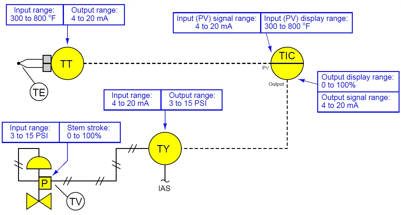
For example, if a engineer is assigned a temperature transmitter with a range of 300 to 800 degrees Fahrenheit, not only does the transmitter have to output 4 mA when sensing 300 oF and output 20 mA when sensing 800 oF, but the controller must display an indication of 300 oF when it receives a 4 mA signal from the transmitter, and display an indication of 800 oF when it receives a 20 mA signal from the transmitter. None of this happens on its own – the engineer must range the transmitter for 300-800 oF input (and 4-20 mA output) as well as range the controller to display 300-800 oF over its 4-20 mA input scale.
Instrument Ranging
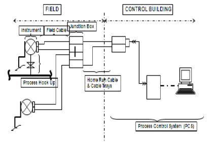
A typical loop is shown here with all instrument ranges displayed:
Analog (non-“smart”) transmitters, I/P transducers, and valve positioners are ranged using “zero” and “span” adjustments, typically screws or nuts. The ranging of analog instruments is discussed in the “Instrument Calibration” topic. Click Here.
Digital (“smart”) transmitters and valve positioners are ranged by setting LRV and URV parameters using a “communicator” device or a personal computer equipped with the appropriate interface and software. This tool is discussed in this article. Click Here
Digital electronic loop controllers contain parameters specifying the process variable (PV) ranges. The following page lists examples of PV range configuration parameters for several different makes and models of loop controllers.
Examples
Siemens/Moore 352 controller:
Process variable range parameters are located in the “Operator’s Display” function block (FB15):
- LRV = Process Lo
- URV = Process Hi
Siemens/Moore 352P and 353 controller:
Process variable range parameters are located in the “Analog Input” function block (AIN):
- LRV = Minscale
- URV = Maxscale
Emerson DeltaV DCS:
Process variable range parameters are located in the “Analog Input” function block (AI) and “PID” function block (PID):
(AI block) = the OUT SCALE parameter contains both high and low range limits, engineering units (e.g. deg F), and decimal point position. The L Type parameter needs to be set to “indirect” to allow scaling to occur (“direct” mode prohibits scaling), and the XD Scale parameter needs to be ranged 0 to 100%. Note that the “direct” and “indirect” options for L Type have absolutely nothing to do with “direct” and “reverse” PID controller action, which is configured elsewhere.
(PID block) = the PV SCALE parameter contains both high and low range limits, engineering units (e.g. deg F), and decimal point position. Note: the PID block’s PV SCALE range must exactly match the OUT SCALE range of the AI block!
Honeywell UDC 2500 controller:
Process variable input #1 range parameters are located in the “Input 1” set-up group of parameters:
- LRV = IN1 LO
- URV = IN1 HI
Automation Direct “SOLO” controller:
Process variable range parameters are located in the following registers:
- LRV = P3-4 Input Range Low
- URV = P3-3 Input Range High
Allen-Bradley PLC5, SLC500, and MicroLogix controllers:
Process variable scaling parameters are typically located either in a “Scale” instruction (SCL) or a “Scale with Parameters” instruction (SCP). In either case, the instruction takes the raw count value from the input channel’s analog-to-digital converter and scales it into the desired process variable display range. Note: SCP instruction parameters may be edited online.
For this reason, downloading edits is not necessary for the MicroLogix PLCs. In fact, it is very important that you not save or download the PLC program, because doing so may alter the PLC’s network address and lead to communication problems. Just make the changes while the PLC is in “Run” mode and then exit the program:
- (SCL instruction) = Rate and Offset values scale the signal according to the slope-intercept formula y = mx + b, where Rate is 10000m and Offset is b
- (SCP instruction LRV) = Scaled Min.
- (SCP instruction URV) = Scaled Max.
Allen-Bradley Logix5000 controller:
Process variable scaling parameters are located in the “PID” instruction (PID):
- LRV = .MINS
- URV = .MAXS
caSCADA “pid” control program:
Process variable scaling parameters are located in one of the source code files which must be modified using a text editor program, then recompiling the pid program so the new parameters may take effect. This control program may be initiated from the Linux command line by typing ./pid and pressing the Enter key, after which a set of instructions will appear on the screen showing the default LRV and URV range values, and which file to find these parameters within. After editing and saving this file, you will need to type make at the Linux command line and press Enter to recompile the program. Finally, type ./pid and press Enter to initiate the recompiled program.
- LRV = pid[0].LRV
- URV = pid[0].URV file
Interest to add any further points? Share with us through below comments section.
Read Next:
- PLC Scan Time
- Process Control Instrumentation
- Strain Gauge Bridge Circuit
- Instrument Cable Voltage Drop
- Types of Thermometers
- Electrical Signal Types
Credits: Tony R. Kuphaldt