Inst ToolsInst ToolsInst Tools
  • Courses
  • Automation
    • PLC
    • Control System
    • Safety System
    • Communication
    • Fire & Gas System
  • Instrumentation
    • Design
    • Pressure
    • Temperature
    • Flow
    • Level
    • Vibration
    • Analyzer
    • Control Valve
    • Switch
    • Calibration
    • Erection & Commissioning
  • Interview
    • Instrumentation
    • Electrical
    • Electronics
    • Practical
  • Q&A
    • Instrumentation
    • Control System
    • Electrical
    • Electronics
    • Analog Electronics
    • Digital Electronics
    • Power Electronics
    • Microprocessor
  • Request
Search
  • Books
  • Software
  • Projects
  • Process
  • Tools
  • Basics
  • Formula
  • Power Plant
  • Root Cause Analysis
  • Electrical Basics
  • Animation
  • Standards
  • 4-20 mA Course
  • Siemens PLC Course
Reading: Formulas to calculate mA from PV, LRV and URV
Share
Font ResizerAa
Inst ToolsInst Tools
Font ResizerAa
  • Courses
  • Design
  • PLC
  • Interview
  • Control System
Search
  • Courses
  • Automation
    • PLC
    • Control System
    • Safety System
    • Communication
    • Fire & Gas System
  • Instrumentation
    • Design
    • Pressure
    • Temperature
    • Flow
    • Level
    • Vibration
    • Analyzer
    • Control Valve
    • Switch
    • Calibration
    • Erection & Commissioning
  • Interview
    • Instrumentation
    • Electrical
    • Electronics
    • Practical
  • Q&A
    • Instrumentation
    • Control System
    • Electrical
    • Electronics
    • Analog Electronics
    • Digital Electronics
    • Power Electronics
    • Microprocessor
  • Request
Follow US
All rights reserved. Reproduction in whole or in part without written permission is prohibited.
Inst Tools > Blog > Basics > Formulas to calculate mA from PV, LRV and URV

Formulas to calculate mA from PV, LRV and URV

Last updated: April 20, 2019 2:55 pm
Editorial Staff
Basics Formulas
11 Comments
Share
2 Min Read
SHARE

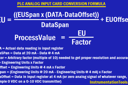
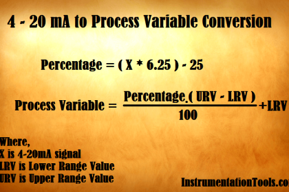
The formula for calculating equivalent current (ma) from known process variable (PV), Lower range value (LRV) and Upper range value (URV).

Formula to calculate mA from PV

Formulas to calculate mA from PV

The formula is:

4-20mA Current to PV Calculation

SPAN = URV – LRV

Where

PV          =  Process Variable
LRV       =  Low Range Value
URV      = Upper Range Value
ma        = milli ampere

Consider left side of formula for Process variable, LRV of transmitter lower range, Span is the difference between LRV & URV of transmitter ranges.

Consider right side of formula for current (ma), LRV of standard current range .i.e is 4ma,

Span is the difference between LRV (4ma) & URV (20ma) of standard current range

.i.e. 20 – 4 = 16, Using this formula we can calculate ma from pv and as well as pv from ma.

For example: The temperature transmitter range is 0 to 50 deg c and  known current ma is 12 then how to calculate the PV of the transmitter ?

Known values :

LRV =  0
URV =  50
mA = 12mA

Standard mA LRV and URV values are as follows –

LRV = 4mA
URV = 20mA

Span = URV – LRV
Span = 20 – 4
Span = 16

Required :

PV = ?

Formula :

4-20mA Current to PV Calculation

 Solution:

Put Values in Formula

PV – 0         =       mA – 4 

SPAN                 16

SPAN = URV – LRV
SPAN = 50 – 0
SPAN = 50

Current to PV Calculation

PV – 0  =       0.5  * 50

PV  =       0.5  * 50

PV  =    25

Also Read: Instrumentation Formulas

Don't Miss Our Updates
Be the first to get exclusive content straight to your email.
We promise not to spam you. You can unsubscribe at any time.
Invalid email address
You've successfully subscribed !

Continue Reading

How to Convert Cable Size from AWG to Inches
Level Calculation with Remote Seals
How a 4-20mA Transmitter Works?
Closed Tank Remote Seal Capillary type DP Transmitter
Difference between Transmitter and Transducer with Examples
Sink or Source? Normally Open or Normally Closed?
Share This Article
Facebook Whatsapp Whatsapp LinkedIn Copy Link
Share
11 Comments
  • balachandran says:
    January 16, 2016 at 3:28 pm

    Good

    Reply
  • Devidas says:
    August 25, 2016 at 8:31 am

    Dear bhardwaj sir,we have Polmon system.we controlling temp and rh in are bye it system. Now there temp showing wrong when getting 13 mA .but system range is -40 to +60 degree .how many should be there PV temp.

    Reply
    • Rubén Miguel says:
      April 22, 2025 at 6:30 pm

      Let’s assume:
      LRS=4 mA, lower read signal
      URS=20mA, upper read signal
      LRV=-40° (°F or °C), lower range value
      URV=60°, upper range value
      PRS=13mA, present read sigal
      Gain:
      m=(Y2-Y1)/(X2-X1)
      m=(60°-(-40°))/(20-4)
      m=6.25°/mA
      System offset:
      Y=mX+b
      b=Y-mX
      b=60°-6.25°/mA*20mA
      b=-65°
      Process value:
      Y=-6.25°/mA*13mA+(-65)
      Y=16.25° (°F or °C)
      Regards.

      Reply
  • Devidas says:
    August 25, 2016 at 8:34 am

    We calculate PV from mA through u given formula mA convertor .bt temp value getting wrong.plz give me rply.

    Reply
    • S Bharadwaj Reddy says:
      August 28, 2016 at 3:06 pm

      For formula to calculate PV from mA. Click Here

      Reply
  • Gama sonkar says:
    August 29, 2017 at 3:47 am

    Explain in detail

    Reply
  • KM says:
    August 14, 2019 at 12:04 pm

    outstanding
    plz transmitter calibration step by step full process

    Reply
  • Vimal Prasath says:
    January 4, 2020 at 4:15 pm

    Instrument detail

    Reply
  • Muhammad Haroon Asghar says:
    August 17, 2023 at 9:39 pm

    I have another method to calculate at ease of better understanding to everyone,

    For mA =,

    [(16 × Process Value (PV) ÷ Process Span] + 4

    For scalled variable =,

    [{Scalling Span × Process Value; (PV)} ÷ Process Span]

    Reply
  • Ranjeet says:
    April 1, 2025 at 9:10 pm

    20 mA in URV 804mmwc what is the 4 mA

    Reply
    • Spandan Bavishi says:
      May 21, 2025 at 12:21 pm

      160.8

      Reply

Leave a Reply Cancel reply

Your email address will not be published. Required fields are marked *

Stay Connected

128.3kFollowersLike
69.1kFollowersFollow
210kSubscribersSubscribe
38kFollowersFollow

Categories

Explore More

Remote Seal Transmitters Ranging Calculation
Scaling Sensor Output to Engineering Units
Open and Closed Tank Level Calculations
Instrumentation Abbreviations
PLC Analog Input Conversion Formula
Control and Instrumentation Engineer Study Guide
Difference between PFD and P&ID with Example
Example of 3-15 psi to 4-20mA Conversion

Keep Learning

Electrical Conduit

What is Electrical Conduit? Types, Advantages, Disadvantages

What Every Instrument Engineer Should Know

Common Mistakes in Instrumentation

SMART Transmitter

What is a SMART Transmitter?

4-20mA Current Loop

Basics of 4-20mA Current Loop

Basics of Trips, Interlocks, Permissives & Sequences

Basics of Trips, Interlocks, Permissives & Sequences

Two wire loop powered transmitters

4-20 mA Transmitter Wiring Types : 2-Wire, 3-Wire, 4-Wire

Instrumentation Dictionary

Instrumentation Dictionary

Turbine Flow meter coefficient

Turbine Flow Meter Coefficient and Scaling Factor

Learn More

Time Response Analysis

Effect of Adding a Zero to a System – II

PLC Automatic Pedal Switch for Speed Control

PLC Automatic Pedal Switch for Speed Control

Card Failures in Automation Panels

Automation Panel Electronic Cards Failure investigation

Simple Three Digital Electronic Project Ideas

Simple Three Digital Electronic Project Ideas

Convert-Percentage-to-current

Convert Percentage (0-100%) to current (4-20mA)

Siemens PLC

Five Types of PLC Programming languages

4-20mA Current Loop

Basics of 4-20mA Current Loop

How to Download Rslogix Free

Download Allen Bradley RSLogix PLC Software

Menu

  • About
  • Privacy Policy
  • Copyright

Quick Links

  • Learn PLC
  • Helping Hand
  • Part Time Job

YouTube Subscribe

Follow US
All rights reserved. Reproduction in whole or in part without written permission is prohibited.
Welcome Back!

Sign in to your account

Username or Email Address
Password

Lost your password?