Inst ToolsInst ToolsInst Tools
  • Courses
  • Automation
    • PLC
    • Control System
    • Safety System
    • Communication
    • Fire & Gas System
  • Instrumentation
    • Design
    • Pressure
    • Temperature
    • Flow
    • Level
    • Vibration
    • Analyzer
    • Control Valve
    • Switch
    • Calibration
    • Erection & Commissioning
  • Interview
    • Instrumentation
    • Electrical
    • Electronics
    • Practical
  • Q&A
    • Instrumentation
    • Control System
    • Electrical
    • Electronics
    • Analog Electronics
    • Digital Electronics
    • Power Electronics
    • Microprocessor
  • Request
Search
  • Books
  • Software
  • Projects
  • Process
  • Tools
  • Basics
  • Formula
  • Power Plant
  • Root Cause Analysis
  • Electrical Basics
  • Animation
  • Standards
  • 4-20 mA Course
  • Siemens PLC Course
Reading: Inherent vs Installed Control Valve Flow Characteristics
Share
Font ResizerAa
Inst ToolsInst Tools
Font ResizerAa
  • Courses
  • Design
  • PLC
  • Interview
  • Control System
Search
  • Courses
  • Automation
    • PLC
    • Control System
    • Safety System
    • Communication
    • Fire & Gas System
  • Instrumentation
    • Design
    • Pressure
    • Temperature
    • Flow
    • Level
    • Vibration
    • Analyzer
    • Control Valve
    • Switch
    • Calibration
    • Erection & Commissioning
  • Interview
    • Instrumentation
    • Electrical
    • Electronics
    • Practical
  • Q&A
    • Instrumentation
    • Control System
    • Electrical
    • Electronics
    • Analog Electronics
    • Digital Electronics
    • Power Electronics
    • Microprocessor
  • Request
Follow US
All rights reserved. Reproduction in whole or in part without written permission is prohibited.
Inst Tools > Blog > Control Valves > Inherent vs Installed Control Valve Flow Characteristics

Inherent vs Installed Control Valve Flow Characteristics

Last updated: July 25, 2019 7:23 am
Editorial Staff
Control Valves
1 Comment
Share
5 Min Read
SHARE

What is inherent characteristic of a valve ?

The inherent characteristic of a valve is the characteristic published by the manufacturer, based on tests performed in a system where great care is taken to ensure that the pressure drop across the test valve is held constant at all valve openings and flow rates.

Contents
What is inherent characteristic of a valve ?What is Installed characteristic of a valve ?Inherent vs Installed Control Valve Flow Characteristics

The inherent characteristic, therefore, represents the relationship between valve flow capacity and valve opening when there are no system effects involved

What is Installed characteristic of a valve ?

The installed characteristic is the plot of flow against opening of valve using actual pressure drops experienced in practice.

Due to the fact that in most applications the pressure drop increases as the flow rate drops, the installed characteristic will normally change from =% towards linear, and from linear towards quick opening.

Inherent vs Installed Control Valve Flow Characteristics

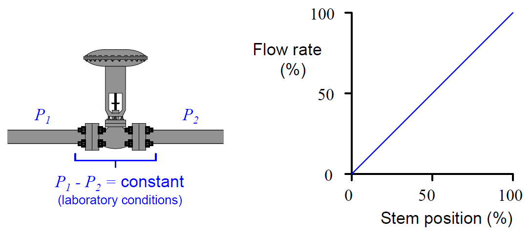
When control valves are tested in a laboratory setting, they are connected to a piping system providing a nearly constant pressure difference between upstream and downstream (P1 − P2 = constant).

With a fluid of constant density and a constant pressure drop across the valve, flow rate becomes directly proportional to the valve’s flow coefficient (Cv).

This is clear from an examination of the basic valve capacity equation, if we replace the pressure and specific gravity terms with a single constant k:

Control Valve Sizing Formula

(If pressures and specific gravity are constant . . .)

Q = k.Cv

As discussed in an earlier article, the amount of “resistance” offered by a restriction of any kind to a turbulent fluid depends on the cross-sectional area of that restriction and also the proportion of fluid kinetic energy dissipated in turbulence.

If a control valve is designed such that the combined effect of these two parameters vary linearly with stem motion, the Cv of the valve will likewise be proportional to stem position.

That is to say, the Cv of a “linear” control valve will be approximately half its maximum rating with the stem position at 50%; approximately one-quarter its maximum rating with the stem position at 25%; and so on.

If such a valve is placed in a laboratory flow test piping system with constant differential pressure and constant fluid density, the relationship of flow rate to stem position will be linear.

With constant pressure drop, the flow rate through any valve is directly proportional to that valve’s Cv, and with a “linear” valve design the Cv (and therefore the flow rate as well) must be directly proportional to stem position:

Inherent vs Installed Control Valve Flow Characteristics

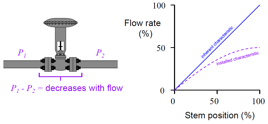
However, most real-life valve installations do not provide the control valve with a constant pressure drop. Due to frictional pressure losses in piping and changes in supply/demand pressures that vary with flow rate, a typical control valve “sees” substantial changes in differential pressure as its controlled flow rate changes.

Generally speaking, the pressure drop available to the control valve decreases as flow rate increases.

The result of this pressure drop versus flow relationship is that the actual flow rate of the same valve installed in a real process will not linearly track valve stem position. Instead, it will “droop” as the valve is further opened.

This “drooping” graph is called the valve’s installed characteristic, in contrast to the inherent characteristic exhibited in the laboratory with constant pressure drop:

Control Valve Flow Characteristics

Each time the stem lifts up a bit more to open the valve trim further, flow increases, but not as much as at lower-opening positions. It is a situation of diminishing returns, where we still see increases in flow as the stem lifts up, but to a lesser and lesser degree.

I have found this concept of “installed characteristic” to be especially challenging for many engineers. In the interest of clarifying the concept, the next two subsections will present a pair of contrasting valve performance scenarios.

They are :
  1. Control Valve Performance with Constant Pressure

  2. Control Valve Performance with Varying Pressure

Don't Miss Our Updates
Be the first to get exclusive content straight to your email.
We promise not to spam you. You can unsubscribe at any time.
Invalid email address
You've successfully subscribed !

Continue Reading

Short Notes on Different Valve Types
Solenoid Valve with Manual Reset Working Principle
Valve Basics, Sizing, and Actuators Books
Top 80+ Valve Questions and Answers
Emergency Shutdown Valve : Advantages
Types of Valve Actuators
Share This Article
Facebook Whatsapp Whatsapp LinkedIn Copy Link
Share
1 Comment
  • NGUYEN QUANG KHAI says:
    October 11, 2018 at 11:05 am

    Dear Mr. S Bharadwaj Reddy,

    Thank you very for your great series posts about Control Valve.

    I was wondering if the Flow Coefficient (Cv or Kv) should be independent on operating conditions Pressure and Flow rate. In the other work, the values of Kv at each valve opening should be const no matter if the inherent condition occurs or not.

    Look forward to hearing from you soon.

    Best regards,
    Nguyen Quang Khai,
    Offshore Plant System Lab
    Dept. of Naval Architecture & Ocean Engineering
    Pusan National University
    Cellphone: +82 10 3419 1803

    Reply

Leave a Reply Cancel reply

Your email address will not be published. Required fields are marked *

Stay Connected

128.3kFollowersLike
69.1kFollowersFollow
210kSubscribersSubscribe
38kFollowersFollow

Categories

Explore More

Why we Require Dual SOV on a Control Valve?
What are Isolation valves? – Purpose, Types, Configurations
Difference between PCV and PRV
Root Cause Analysis for Tank Overflow due to Valve Problem
What is Needle Valve ?
Solving Control Valve Hunting: Instrument Troubleshooting
Control Valve Performance with Constant Pressure
Control Valve Recommended Practices for Harsh Process Conditions

Keep Learning

port-guided globe valve plug

What is Port-guided Globe Valve ?

Pneumatic Piping Design and Specification

Pneumatic Piping Design and Specification

Globe Valve Parts

What is Globe Valve ?

Control Valve Actuator Parts

Reversing Control Valve Actuator Fail Safe Mode

Control Valve Working Animation

Control Valve Working Animation

cavitation-control valve trim

What is Control Valve Cavitation ?

Emergency Block Valve

SIS Emergency Block Valves (EBV)

Valve Seat leakage Test

Valve Seat Leakage Test

Learn More

Formula of 2 Wire RTD, 3 Wire RTD & 4 Wire RTD

Formula of 2 Wire RTD, 3 Wire RTD & 4 Wire RTD

Pressure Gauge with Syphons

Pressure Gauge Syphons Principle

Stop Check valve

What is Stop Check valve ?

DCS Alarm Summary Dashboard using Microsoft Power BI

DCS Alarm Summary Dashboard using Microsoft Power BI

Metering pumps

Metering Pumps

Electrical Conduit

What is Electrical Conduit? Types, Advantages, Disadvantages

Voice Activated Industrial Automation

Voice Activated Industrial Automation Systems

Differential Pressure Switch Principle

Differential Pressure Switch Principle

Menu

  • About
  • Privacy Policy
  • Copyright

Quick Links

  • Learn PLC
  • Helping Hand
  • Part Time Job

YouTube Subscribe

Follow US
All rights reserved. Reproduction in whole or in part without written permission is prohibited.
Welcome Back!

Sign in to your account

Username or Email Address
Password

Lost your password?