In this article, we will discuss about digital systems, the importance of digital systems, the design of the system, and its function & Limitations.
Digital Systems
Electronic circuits and systems are of two kinds – analog and Digital. Analog circuits are those in which current and voltages vary continuously through the given range. These analog circuits can take infinite values within the specified range.
On the other hand, a Digital circuit is one in which the voltage levels assume a finite number of distinct values. The difference between analog and digital circuits is not so much in the types of semiconductor devices used in these circuits as it is in voltage and current variations that occur when each type of circuit performs its own function as per the design.
Digital circuits are often called switching circuits because these voltage levels will be switched from one value to another value very quickly. Transition time is assumed to be zero here. Digital circuits are called logic circuits because each of these circuits obeys a certain set of logical rules. The manner in which a logic circuit responds to an input is referred to as the circuit’s logic.
Digital circuits are commonly used in computational circuits, data processing, control systems, communications, and measurement. These digital circuits have a greater advantage than analog systems.
Why Digital Systems were preferred over Analog Systems?
Following are some of the important reasons why digital systems were preferred over analog systems:
Digital systems are easier to design
Digital systems have only two voltage levels for switching, High and Low which are easier to design. The accurate numerical value is not required here because it has logical significance only, so the range where they fall tends to be very important.
But Analog systems have a significant numerical value, which makes the system complicated for designing.
Information storage is easy
There are many types of semiconductors and magnetic memories of large capacities which can store a large amount of digital data for a long period.
Accuracy and Precision are greater
Digital system is more accurate than analog systems because we can expand the digital system easily by adding switching circuits with them. But the analog circuit is complex and costly for the same accuracy and precision.
More Versatile
The operation in the circuits can be controlled by a set of instructions called a program. At any point, the operation of the system is to be changed by modifying the program.
Though the program is changed, the design of the system need not be updated so much. Just a minor change is required, this digital system will adopt the program to do the function.
Even though the analog system can also be programmed, the variety of the available operation is severely limited.
Less affected by noise
Unwanted electrical in the circuit is considered as noise. We cannot avoid noise in any system. In the digital system, the range of voltage value is only important so it will not be crucial in a digital system.
But in the analog system, we need the exact values so small noise will disturb the nominal value in the analog system which may cause a system error. Comparatively, a Digital system is less affected by noise than an analog.
More digital circuits can be fabricated on IC chips
Fabrication of digital IC is very simple than analog ICs. We can achieve high-density integration in digital ICs than Analog ICs.
Because digital ICs do not require high-value capacitors, resistors, precision inductors, and transformers like the analog design.
Design of Digital Systems
Digital system design is mainly classified into three categories. They are System Design, Logic Design, and Circuit Design. System Design involves breaking the overall systems into subsystems and also it specifies the characteristics of each and every subsystem.
For example, the system design of digital computers involves specifying the number and type of memory units, arithmetic units, input and output devices, and also interconnection between the control part of the subsystem.
Logic Design involves the connection between the logical building blocks to do a specific task. For example, logic design determines the connection between flip flops and logic gates and performs a binary addition or subtraction.
And last is a circuit design, which mainly constitutes the physical components like resistors, diode, and transistors to form a gate for performing the logical operation and systems operation.
Functions of Digital Logic
We can perform many operations in the digital system with the help of Logic gates and Flip flops.
Some of the common operations are Arithmetic operations, code conversions, encoding, multiplexing, demultiplexing, counting, and storing.
Arithmetic Operations
We can perform basic arithmetic operations like addition, subtraction, multiplication, and division with these digital systems. The arithmetic operation addition is performed by a digital circuit with the logic called an adder.
The main objective of this adder function is to add two numbers addend (A) and augend (B) with a carry input (CI) for generating a sum term (S) and to carry an output term (CO).
Same as addition we can perform subtraction by a digital circuit called a subtractor. Its function is to subtract the subtrahend (A) from the minuend (B) with consideration of borrow input (BI) to generate difference term(D) also a borrow output term (BO).
As the subtraction function is equivalent to the addition of a negative number, subtraction can be performed by using an adder also.
Multiplication operation was performed by the logic circuit called Multiplier. This multiplier function is to multiply the multiplicand (A) by the multiplier (B) to generate the product term (P).
Since Multiplication is a series of additions with shifts in the position of the partial products, it can be also performed by adders also.
The last arithmetic operations are division, this operation is done by the logical circuit called a divider. Its function is to divide the dividend (A) by the divisor (B) for generating the quotient term (Q) and remainder term (R).
Division can also be performed by an adder itself since division involves a series of subtractions and shifts.
Encoding
Encoding is the process of converting some popular or non-linear number to the coded form. This encoding function is done by the logical digital circuit called an encoder.
The encoder receives the digits (decimal, hexadecimal, or octal) or alphabets, or special symbols and converts them into the respective binary code.
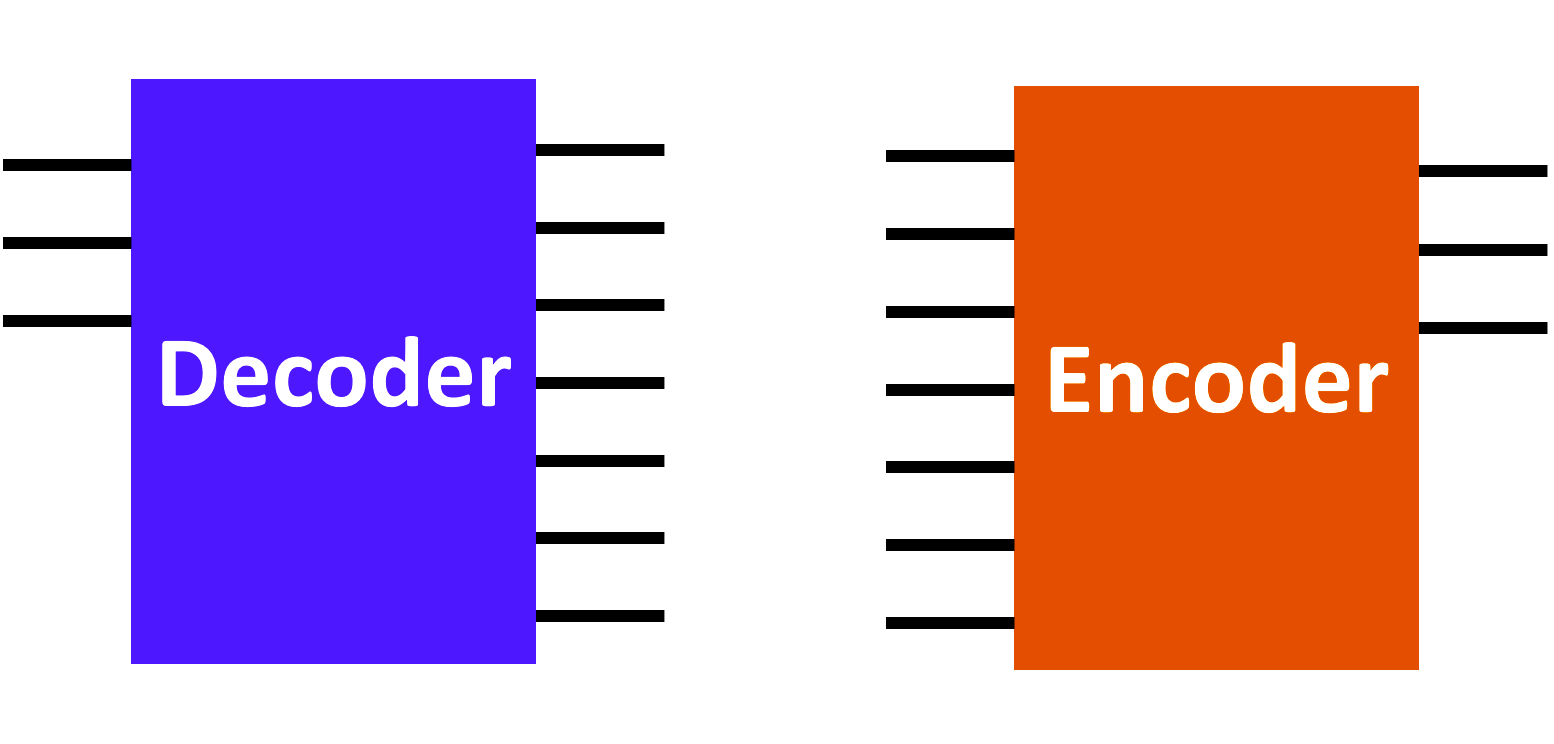
Decoding
Decoding is the inverse process of encoding. The decoder is the device that makes the decoding operation.
The decoder converts the binary-coded information to unique outputs such as decimals, octal, digits, or symbols.
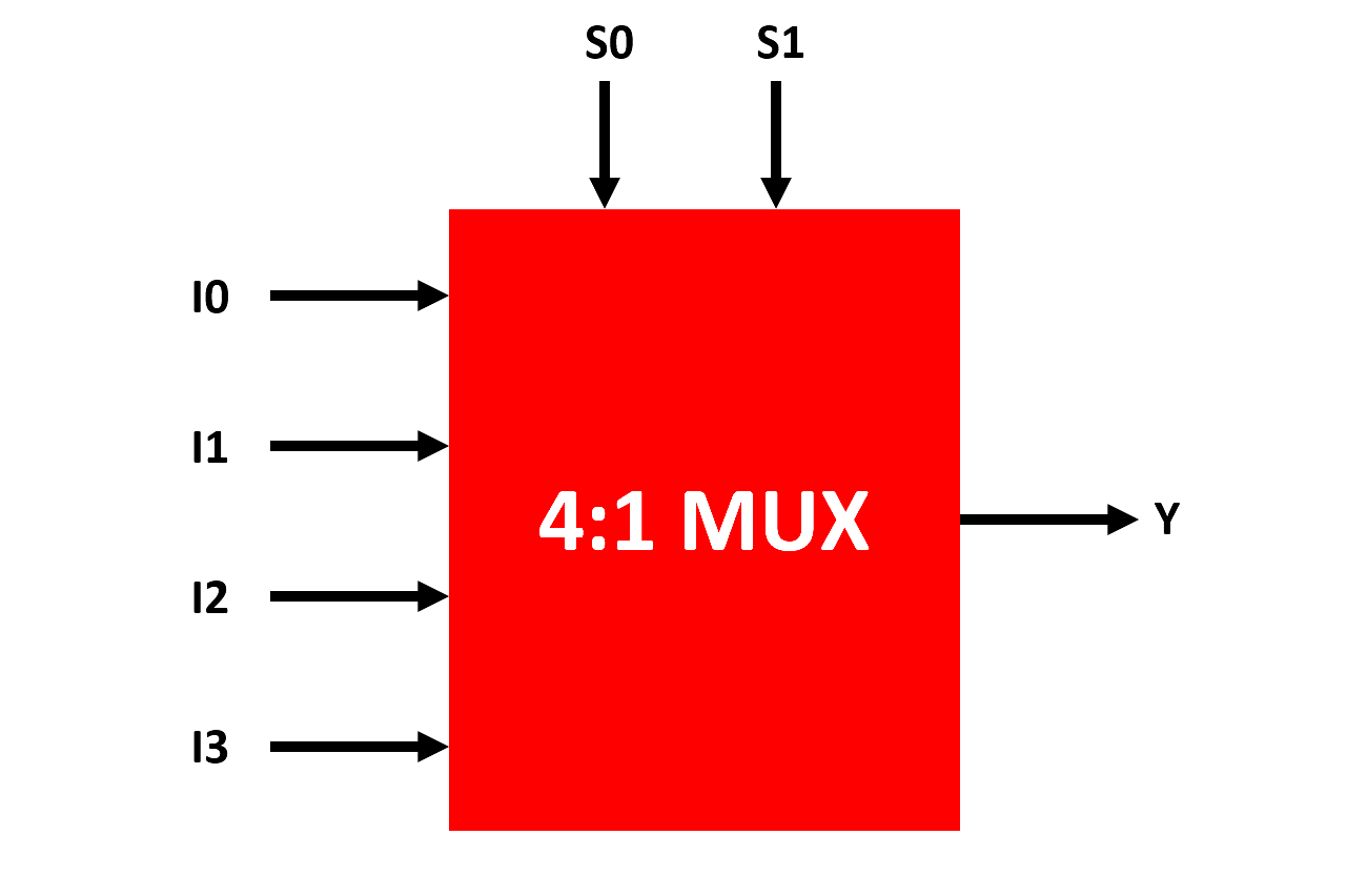
Multiplexing
Multiplexing means sharing. It is the process of switching information from several lines into a single line in a single sequence.
The multiplexer is a logic circuit that accepts several data inputs and allows only one of them for the output. It is an N to 1 device which means N number of inputs to 1 output.
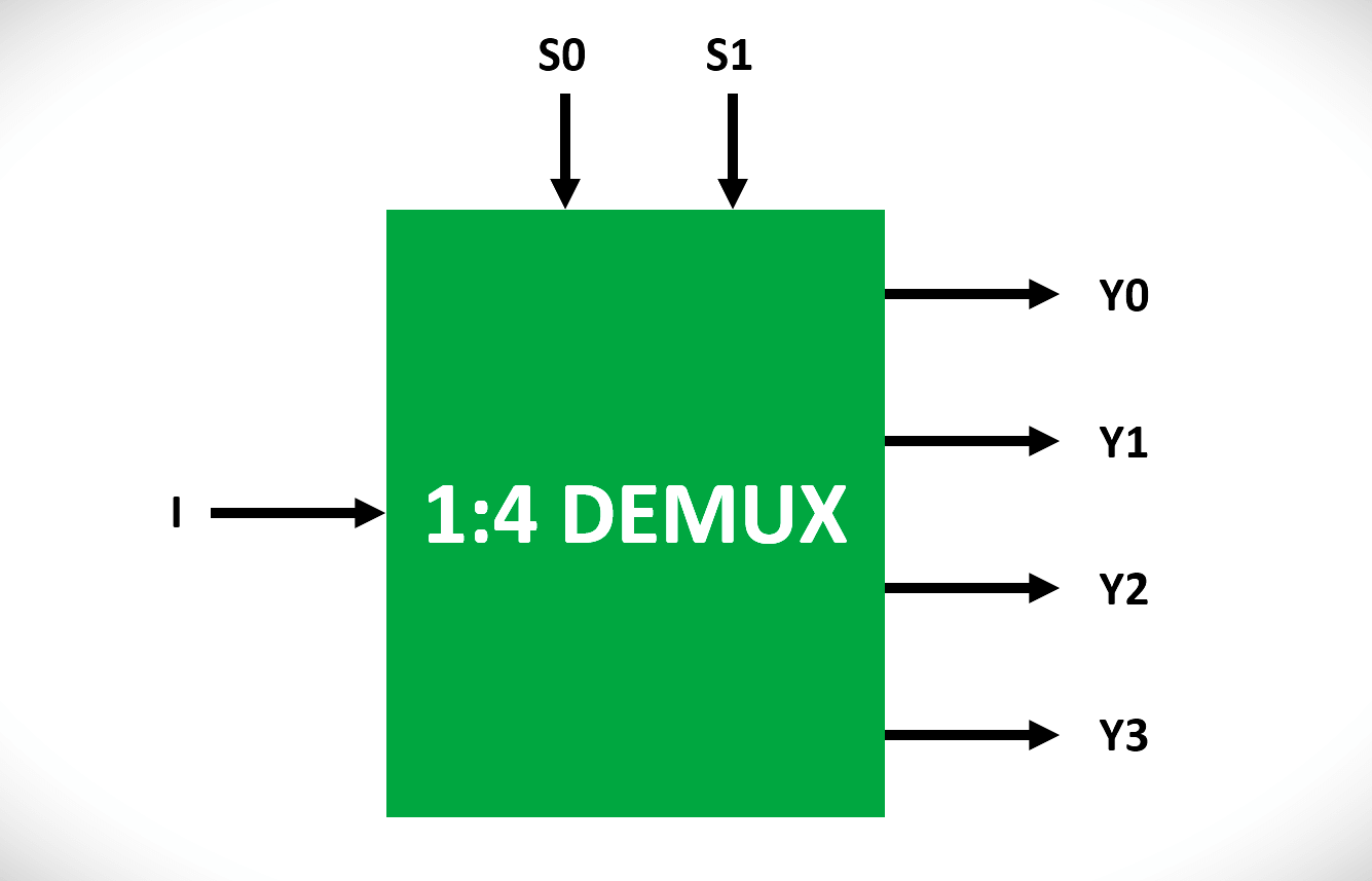
Demultiplexing
Demultiplexing is the inversion of multiplexing. It is the process of switching information from one input to many outputs as per the logic.
A demultiplexer is a digital circuit that takes a single input and distributes it over several outputs. It is also known as a 1 to N device which means sharing 1 input to N number of outputs.
Code Conversion
A logic circuit used to convert information coded in one form to another form is called a code converter.
In this logic, we can easily convert BCD code into an XS-3 code form.
Storage
Storing information is very essential in digital systems. In Digital systems information were stored in a temporary storage area called Registers.
Registers are made up of storage elements called Flip Flops. All the data is stored by giving the clock pulse to the flip flop which makes the data storage.
Depending on the number of Flip Flops in the system, the clock pulse was made for processing.
Counting
Counter operation is very important in digital systems. The logic circuit used to count the number of pulses inputted on it is called a counter.
The pulse may represent some events depending on the input signal. In order to count, the counter must remember the present number by that it can go to the next proper number in the sequence when the next pulse comes.
So storage elements needed to include in the counter for storing the present number in the system.
Frequency Division
A counter can also be used to perform Frequency division. To divide a signal of frequency f by N, the signal is applied to a counter.
The output of the counter will be of Frequency f / N.
Data Transmission
The most common operation in digital systems is data transmission from one place to another. Depending on the distance the data may be transferred very small or very large.
The information transmission is in binary form, representing voltages at the outputs of a sending circuit which are connected to the inputs of a receiving circuit.
This data is transmitted by two basic methods, Serial transmission, and Parallel transmission.
In parallel data transmission, all the bits are transmitted simultaneously. So, one connecting line is required for each bit. Though data transmission is faster in this parallel connection but the number of lines used between the transmitter and receiver is more.
A parallel transmission system is complex and costly compared to a serial transmission system. By Serial transmission method, the information is transmitted bit-by-bit. So, one line is used for connecting the transmitter and the receiver.
Since the data is transmitted through a single line, this serial transmission is cheaper and simple to design but the transmission rate will be slow compared to the parallel transmission.
Limitations of the Digital Systems
Even though digital systems have numerous advantage it has one major limitation. Most physical quantities are physical in nature. These quantities are often the inputs and also outputs that are continually monitored, controlled, and operated by a system.
When these quantities are processed and expressed digitally, we are converting this analog into digital form. Because of this conversion, the processing time increases and the system became more complex & working cost is also comparatively high. So, this drawback limits all the advantages of the digital system.
Both analog and digital techniques can be employed in the same system to get greater advantages. This type is called a Hybrid system. But the tendency today is towards employing digital systems because the economic benefits of integration are of overriding importance.
If you liked this article, then please subscribe to our YouTube Channel for Electrical, Electronics, Instrumentation, PLC, and SCADA video tutorials.
You can also follow us on Facebook and Twitter to receive daily updates.
Read Next:
- Applications of Robots
- Feedback Control System
- Motor Control using Modbus
- Variable Frequency Drive (VFD)
- Meters in Electrical Equipment