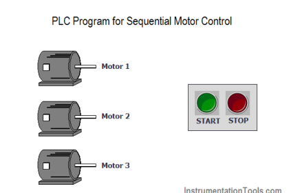
A PLC has been programming to control the starting and stopping of a three-phase electric motor.
The program is supposed to require that the operator press and hold the “Start” pushbutton for at least three seconds before the motor starts and runs.
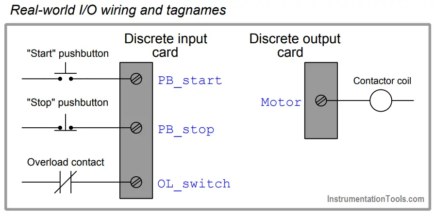
Shown here is a partial wiring diagram and offline PLC program display for the system:
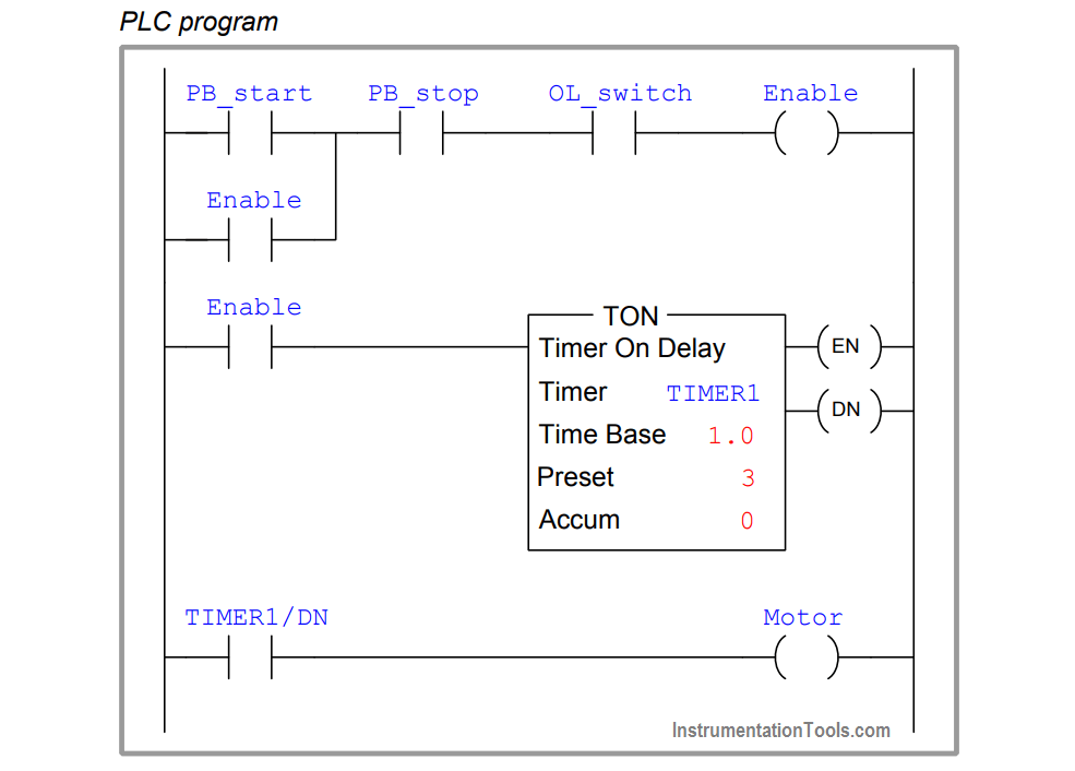
Identify the problem(s) in this PLC program, and modify it so that it will work as it should.
Answer :
The way it’s programmed right now, the “Start” pushbutton does not need to be held for three seconds – just pressing it momentarily is enough to start the motor.
The motor, however, does delay for three seconds before starting.
In other words, there is a three-second time delay in effect, but it’s not requiring the “Start” switch be continuously pressed for that long.
All the time delay is doing is delaying the start-up of the motor after the “Start” switch has been momentarily pressed.
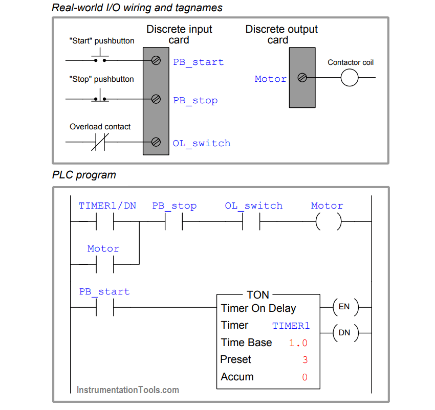
Here is a functional solution:
If you liked this article, then please subscribe to our YouTube Channel for PLC and SCADA video tutorials.
You can also follow us on Facebook and Twitter to receive daily updates.
More PLC Questions :

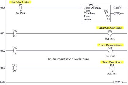
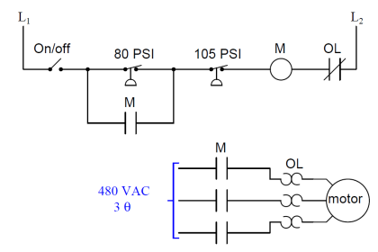


Also stop PB and OLR should be taken NC contact