Inst ToolsInst ToolsInst Tools
  • Courses
  • Automation
    • PLC
    • Control System
    • Safety System
    • Communication
    • Fire & Gas System
  • Instrumentation
    • Design
    • Pressure
    • Temperature
    • Flow
    • Level
    • Vibration
    • Analyzer
    • Control Valve
    • Switch
    • Calibration
    • Erection & Commissioning
  • Interview
    • Instrumentation
    • Electrical
    • Electronics
    • Practical
  • Q&A
    • Instrumentation
    • Control System
    • Electrical
    • Electronics
    • Analog Electronics
    • Digital Electronics
    • Power Electronics
    • Microprocessor
  • Request
Search
  • Books
  • Software
  • Projects
  • Process
  • Tools
  • Basics
  • Formula
  • Power Plant
  • Root Cause Analysis
  • Electrical Basics
  • Animation
  • Standards
  • 4-20 mA Course
  • Siemens PLC Course
Reading: How to tune a PID Controller ?
Share
Font ResizerAa
Inst ToolsInst Tools
Font ResizerAa
  • Courses
  • Design
  • PLC
  • Interview
  • Control System
Search
  • Courses
  • Automation
    • PLC
    • Control System
    • Safety System
    • Communication
    • Fire & Gas System
  • Instrumentation
    • Design
    • Pressure
    • Temperature
    • Flow
    • Level
    • Vibration
    • Analyzer
    • Control Valve
    • Switch
    • Calibration
    • Erection & Commissioning
  • Interview
    • Instrumentation
    • Electrical
    • Electronics
    • Practical
  • Q&A
    • Instrumentation
    • Control System
    • Electrical
    • Electronics
    • Analog Electronics
    • Digital Electronics
    • Power Electronics
    • Microprocessor
  • Request
Follow US
All rights reserved. Reproduction in whole or in part without written permission is prohibited.
Inst Tools > Blog > Control Systems > How to tune a PID Controller ?

How to tune a PID Controller ?

Last updated: September 29, 2018 10:40 pm
Editorial Staff
Control Systems
2 Comments
Share
5 Min Read
SHARE

What PID stands for?

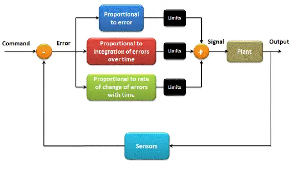
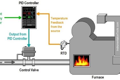
It stands for Proportional, Integral, and Derivative controller. It’s a mathematical description of the way you think. PID helps you automatically achieve your goal, exactly the same way you used to do it manually. This diagram shows a general structure for a PID controller.

PID Controller Tuning

So, what do you need to form a PID controller?

You need the following six basic elements:

  • Error: It is the difference between your command and the output of the controller.
  • Proportional term P: It is a constant directly related to the amount of error. If you have large error, this term gives you a large output. And if you have a small error, it’ll give you a small output, that simple! The P term affects the speed to reach your target.
  • Integral term I: It is a constant related to the integration (summation) of errors over time. If your error is increasing, this term gives you a large output. However, if the error is decreasing, the I term gives you a small output. Thus it’s used to fine tune your results, i.e., when you almost reach your goal, the P term cannot serve you anymore (actually it works against you here!), the I term is the one you can count on to drive you error signal to zero.
  • Derivative term D: It is a constant related to the rate of change (derivative) of errors with time. What does this mean? It means that if your error signal changes rapidly, i.e., you have a highly dynamic system like a multi copter, the D term will give you higher output to catch up with the changes. On the other hand, if your error changes slowly, like in the room temperature example, the D term won’t find anything fast enough to amplify. Thus it’ll look for your noise signal (which usually has a high frequency) and amplify it to make your life miserable! The D term is a very dangerous controller if it’s not tuned perfectly!
  • Limits: You need to limit the output of each of the previous controllers!
  • Finally, you need your system of course! Unless you’re satisfied with simulations.

So, how do you tune your PID parameters to the optimal response?

Most often tuning is an art more than a science. Observe the system and use your intuitive guess and logical reasoning. Here are seven golden rules for general PID tuning:
  1. After nulling all the parameters, increase the P term so that the output reaches the target in the shortest possible time.
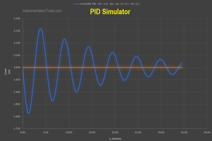
  2. If your output starts oscillating, it means you have too much P. Lower your P term until the oscillation disappears. You’ll end up slightly higher or lower than your target. Don’t worry; we’ll fix that in the next step.
  3. Now, increase I term slightly until your error goes away. Note that usual I values are very small (in the order of one thousandth for example) and they’re dependent on the update rate of your PID loop. The I term is very useful when you have outside error signals affecting your system (e.g. wind in a multi copter). It drives your error to zero whenever possible.
  4. If you feel your output is oscillating and it was not before you adjusted your I term, lower I slightly.
  5. For many slow dynamic systems, your job is almost done! You just have to jump to the last step.
    When dealing with highly dynamic systems, however, you need to adjust the D term. If you feel your output “lagging” behind the error variations and trying hard but failing to catch them, increase this term slightly.
  6. If your system starts to oscillate with high frequency and small transitions, you probably have too much D term which is amplifying your noise. Decrease D appropriately. If your system,however, has too much noise, it’s better to keep this parameter to zero.
  7. Last but not least, watch your limits! If you were changing the previous parameters without any noticeable change in the output, remember that limits cut down your output signal. Increase them probably, but be careful not to burn or saturate your system.

Also Download: PID Controller Simulator

Don't Miss Our Updates
Be the first to get exclusive content straight to your email.
We promise not to spam you. You can unsubscribe at any time.
Invalid email address
You've successfully subscribed !

Continue Reading

Process Control Instrumentation
SCADA & Telemetry Systems
ICS Control System Security
ICS System Design Considerations
Speed Control of Ship Electrical Motor Propulsion
Types of SCADA System Architecture
Share This Article
Facebook Whatsapp Whatsapp LinkedIn Copy Link
Share
2 Comments
  • ch.prasad says:
    July 5, 2016 at 9:46 am

    if you don’t mind i need practically values by using can you give the graph of pid theory and practical graph

    Reply
    • John Lilipaly says:
      February 2, 2023 at 1:24 pm

      OK

      Reply

Leave a Reply Cancel reply

Your email address will not be published. Required fields are marked *

Stay Connected

128.3kFollowersLike
69.1kFollowersFollow
210kSubscribersSubscribe
38kFollowersFollow

Categories

Explore More

Manufacturing Execution System (MES) in Industrial Automation
What is a Surge Protection Device? – Principle, Types, Advantages
Difference between Process shutdown and Emergency Shutdown
Tips for Reducing the Noise Signals
Redundant Automation Systems – Need and Advantages
Difference between SR Flipflop and RS Flipflop ?
Package System Architecture – Control & Instrumentation
How to Export Data from DeltaV System to Excel

Keep Learning

Pre-Engineering Design Documents

Industrial Automation Pre-Engineering Design Documents – Project & Process

Signal Isolator

What is a Signal Isolator? Principle, Advantages, Disadvantages

Select Right Type of Controller

How to Select the Right Type of Controller

Internet of Things (IOT)

History of Internet of Things (IOT)

Integral (Reset) Control Theory

Design & Construction of Process Plant

Process Control Systems Philosophy Concept

Siemens PCS 7

What is PCS 7?

Control System

The need for automatic controls

Learn More

Identify which lamp in the following ladder-logic diagram

Identify High Flow Alarm and Low Flow Alarm?

ESD System Insights

ESD System Insights: Signals for Emergency Valve Shutdown Explained

Fire Extinguishers Mock Test

Fire Extinguishers Mock Test

Centralized vs Decentralized Automation Systems

Centralized vs Decentralized Automation Systems

Put Get PLC communication

PUT Command in Siemens PLC – TIA Portal Basics

Calculate DPT Calibrated Range

Calculate the Transmitter Values

Transmitter Detailed Specifications

Transmitter Detailed Specifications

dissolved-oxygen-probe-calibration-procedure

Dissolved oxygen probe calibration procedure

Menu

  • About
  • Privacy Policy
  • Copyright

Quick Links

  • Learn PLC
  • Helping Hand
  • Part Time Job

YouTube Subscribe

Follow US
All rights reserved. Reproduction in whole or in part without written permission is prohibited.
Welcome Back!

Sign in to your account

Username or Email Address
Password

Lost your password?