This article is about the elements that help to interface a computer with the real-world process through Data Acquisition using sensors and transducers, GPIO cards, and conditioned signals.
What is Data Acquisition?
Real-time interfacing is a term used to describe the aspects of connecting the computer with a real-world process and communicating the data between the two systems. Monitors, keyboards, mouse, and printers are some of the best examples of real-time monitoring systems.
A more general approach is generally interfacing the sensors, actuators, computers, and a real-process. In this process, humans can easily view the real-time process and operations on the computer without visiting the process. We can simply easily that, the sensor is an input device which is like the keyboard in the computer that gives the input data while the actuator is an output device which is like a monitor in the computer which delivers the output process.
This real-time interfacing in many applications is through the Data Acquisition method. It is nothing but collecting the data from the process to display them with the help of screens or monitors through interfacing.
Elements of Data Acquisition
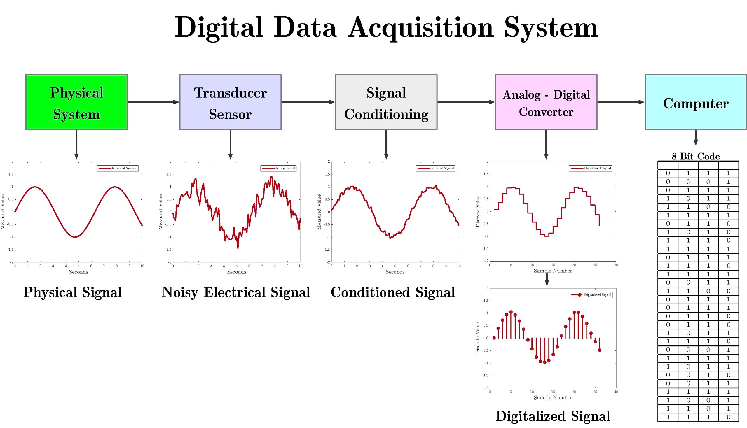
Data acquisition is a collection of add-on hardware and software that allows your computer to receive real-world sensor inputs or data for processing. Though sensors can be based on electrical, mechanical, optical, or other principles, they need to convert their real-world information such as temperature and pressure into low-power electrical signals which can be read by the computer.
After the data is received from the computer side, it will perform some operations like plotting, processing, and writing to a file for doing the operation as per the requirement. A Data Acquisition system also can know to be a monitoring system. It can receive data from a real-world process and display the information. It can also display the features of the data extracted through its processing.
In situations where it is necessary to acquire and process data and to also send data back to the real-time process, through a data acquisition and control (DAC) system. A Data acquisition control (DAC) system is a category of Data Acquisition (DA) that requires both sensors and actuators for doing the process.
The role of the actuator is to convert low-power computer signals into required motion, heat, pressure etc. The most common actuators are electric motors, relays, solenoids, and hydraulic & Pneumatic cylinders.
For example, considering Data Acquisition and Data Acquisition Control in a compressor system to measure the characteristics like Speed-Flow and Pressure at different speed values. The compressor has been connected to a variable speed of motor; the speed of the motor can be controlled by the knob which wants to be changed manually by the user.
Signals from flow, pressure, and speed sensors are connected to the compressor outlet and the motor is read and plotted by a computer. The Data Acquisition system reads and displays the sensors input values and at each speed, the operator must vary the speed knob until the desired speed is reached and then record the sensor readings for flow, speed, and pressure.
In the Data Acquisition system, there is a fair amount of variation in the speed reading due to the speed adjustment at each point by the operator. But in the Data Acquisition Control system, the application can be created by adding an adding actuator that moves the speed knob in response to the signal produced by the computer.
The value of the signal is programmed as a function of the error between the actual speed and desired speed, then the knob will move toward the direction that reduces this error.
Finally, the actual motor speed will get precisely the desired speed. Overall Data Acquisition is used to control and monitor the system with manual movement but in Data Acquisition Control by the movement of difference in desired & actual value the result will be obtained.
Now the ongoing trend is to use a personal computer with DAQ hardware for data acquisition in areas of laboratory research, testing, and measurement, industrial automation & processing, This DAQ (Data Acquisition) hardware acts as an interface between the computer and outside world in the mode of modules that can be connected to the ports of parallel, serial and USB in computer or slot cards like PCI, ISA in the motherboard.
The latest DAQ can connect over wireless and cabled ethernet for remote or distributed DAQ applications.
DAQ systems were depends on the following main items:
- Computer
- Transducers and Sensors
- Signal Conditioning
- DAQ Hardware
- Terminal Panels
- General Purpose Input Output cards
- Software
Input/output (I/O) Process
DAQ devices and computers communicated with real-world applications through this Input and Output. This Input and Output device’s performance was determined by the available computer, DAQ device, communication pattern, and bus architecture.
Nowadays computers have a high-speed processor and high-performance bus architecture so it has the capability of transferring data through Input/output at a high transfer rate. It uses the following methods to do the processing.
- Direct Memory Access (DMA): By this method, the data is transferred between the DAQ device and computer memory without the involvement of the CPU. This method makes DMA the fastest available data transfer mechanism. Also, the processor is not burdened with moving data and so it can be used for performing more complex tasks and processes.
- Interrupt Request (IRQ): This Process depends on the CPU to service data transfer requests. The device notifies the CPU when the data to be transferred is ready. Hence, the data transfer speed is tightly coupled to the rate of the CPU, if the CPU responds quickly then the transfer data will be transmitted quickly.
- Programmed I/O: This is a data transfer method in which the buffer is not used instead of that the computer reads and writes directly to the device. As per the given set of lines, the data transfers with a good transmission rate and gets directly to the device.
- Memory Mapping: This is a method for reading and writing to a device directly from the program, which avoids the overhead of delegating the reads and writes to kernel-level software. Memory will be directly occupied in the software by the data transferred for the operation.
Even though these methods are used to transfer the data, the computer can use the data depending upon the selected data acquisition device and its bus architecture. For example, while PCI and FireWire devices offer both DMA and interrupt-based transfers, PCMCIA and USB devices use interrupt-based transfers. The available hard drive is a limiting factor for real-time storage of large amounts of data.
Hard Drive access time and hard drive fragmentation can significantly reduce the maximum rate at which data can be acquired and streamed to disk. Large space is required for the system while performing high-speed and high-frequency transmission on the system.
In general, the overall communication speed is directly proportional to the clock frequency of the processor chip and the bit length of the bus. It means the bit length and clock frequency is more the communication is also speed.
The overall communication is also inversely proportional to the bit length of the processor, which means if the bit length of the processor is more speed of the communication is low and if the bit length of the processor is low means then the speed of the communication is high.
General Purpose I/O cards (GPIO Card)
The necessary elements for the general I/O process are the PC and Operating system software, general purpose I/O card, software driver, proper terminal cards, and cabling for the GPIO card.
The GPIO card is installed in the free extension slot in the PC BUS. The address of the card is mentioned in both the card and its driver software. The termination panel is connected to the GPIO card by one or more cables. This is the point where the system is ready to operate. If any application is selected for the mechatronic programming tasks, it must be programmed with the open-loop and closed-loop applications.
Most GPIO card manufacturers offer their own Windows-based software for controlling their cards. So these cards only work with defined manufacturers it will not support others. Without these GPIO cards, the source will not gather the respected information from the environment and it will lag the process.
Computer and Software
Computer and software were the important elements in the Data acquisition because all the data gathered from the input source and DAQ devices were processed by the computer only. The computer is the displaying and processing device where all the operations were stored, monitored, and analyzed as per the trends.
The real-world data will not be directly displayed on the computer, it should be modified as the user requirement at the end control. This type of activity is done by the software only.
Software is not the physical property in the elements but it configures and controls the whole data with its internal characterization and gives the finished output for the physical system it gets and analyses the trends in the environment which is monitoring in the computer.
Sensors and Transducers
Sensors and Transducers are the elements that give real-world data to the system. Sensors are used to inspect work, evaluate the conditions of work under progress and facilitate high-level monitoring by the computing system.
Sensors are used to translate a physical phenomenon into an acceptable signal that can be analyzed for decision-making. Intelligent systems use sensors to monitor particular situations influenced by a changing environment and control the operations with corrective actions.
The sensor is nothing but transferring real-world data into an electrical signal. Sensors are also referred to as transducers. They cover a broader range of activities which provides them with the ability to identify environmental inputs.
In transducers, the quantities at the input level and the output level are different. Typical input data could be electrical, mechanical, thermal, and optical. A transducer is an element that is used to convert information from one to another. The change in information is measured easily. By this input data from sensors and transducers the computer process the data which will be used for real-time interfacing.
Signal Conditioning
Sensors and Transducers sense the physical conditions in the environment and produce electrical signals that the DAQ system measures. For example, thermocouples, RTD, and thermistors convert temperature into a digital signal through ADC ( Analog to Digital Converter) can measure.
These sensors and transducers generate the electrical signals that must be optimized for the input range of the DAQ device. This optimization is done by the process of signal conditioning. Signal conditioning is nothing but making a property change in the input signal as per the need of the device and systems.
Some of the major signal conditioning processes are:
- Amplification
- Isolation
- Multiplexing
- Filtering
- Excitation
- Linearization
Amplification
The most common type of conditioning is amplification. Considering the example, low-level thermocouple signals should be amplified to increase the resolution in output and also for the reduction of noise.
The signal should be amplified so that the maximum voltage range of the conditioned signal equals the maximum input of the ADC.
Isolation
Another common signal conditioning application is isolating the transducer signals from the computer for safety purposes. The system needs to be monitored at all times to prevent the system from excess voltage transients.
Isolation ensures that the readings from the plug-in DAQ device are the correct value. If that is wrong there will be the cause of ground potential or common mode voltages error. For preventing the system from the ground loop and excess voltages the signals need to be isolated to get a good output and perfect working operation.
Multiplexing
Multiplexing is the process of measuring several signals from a single measurement device. Signal conditioning hardware conditions the more input signals from different devices convert them into required output by using the single ADC.
The ADC samples one channel and switches to the other as per the function. Multiplexing also moderates the sampling time in an even manner at a good rate since all the inputs are merged in a single ADC device.
Filtering
Filtering is the process of removing unwanted signals from the system. A noise filter is used to maintain the high-frequency rate for getting the maximum accuracy in the DC class signals. If the noise is not filtered means the property will get inverse by decreasing the frequency and resulting accuracy.
Like noise filters, there is a filter called an anti-aliasing filter for removing the useless vibration in AC class signals. However, this filter removes all signal frequencies that are higher than the input bandwidth of the device.
Excitation
Signal conditioning also generates excitation for some transducers. Strain Gauges and thermistors require external voltage or current excitation signals. Signal conditioning modules for these transducers usually provide these signals.
RTD measurements are usually made with a current source that converts the variation with a change in resistance to a measurable voltage
Linearization
Another important signal conditioning process is linearization. In some cases of transducers, a nonlinear response will occur when there is a change in the phenomenon while measuring the measurement.
This linearization is done in the process when the responses from the signals are nonlinear for a period of time. The sample of signals will be taken from the defined time then the linearization routines done on that by the several software.
Conclusion
In this article, we have learned about the aspects of computer interfacing and real-time data acquisition and control. Besides the computer and the real-world system, we also discussed the elements of data acquisition which play the main role in getting data from the environment to display them on a screen. And also about signal conditioners that amplify low-level signals and then isolate and filter them for more accurate measurements.