Refer the below set on Ethernet Communication Interview Questions and Answers. Be prepare for the interview and outsmart everyone in the interview process.
Ethernet Communication Interview Questions

Basics of Ethernet
What is ethernet ?
Ethernet is a local area network (LAN) protocol that was originally developed to link computers. Invented by Bob Metcalfe at Xerox Palo Alto Research Center (PARC) and later refined by Xerox, DEC, and Intel, the Ethernet technology specification was later adopted by the IEEE as standard 802.3.
The original Ethernet specification called for a bus topology over several media types, including coaxial cable. Today’s common Ethernet implementations use four twisted pairs of copper wires, commonly referred to as Category 5 (Cat-5) or Category 6 (Cat-6) cabling, and provide a raw data transfer rate of 10 or 100 megabits per second (Mbps).
A newer Gigabit Ethernet standard, supporting data rates up to 1,000 Mbps, was approved in 1999.
Ethernet is a network that is a very efficient method of transmitting vast amounts of data.
Ethernet is ‘open’ – that is, any device can communicate over ethernet if it adheres to an OSI model that defines how ethernet operates. Multiple protocols can be used over the same network – Modbus and Ethernet I/P can work simultaneously over an ethernet network.
The defined ethernet packet is the key to ethernet’s flexibility – it is simply a method of transmission and is scalable – speeds have increased as technology has improved. Ethernet can work over copper cables, fiber optics and can also use wireless technology. It is simply the best way to communicate in an industrial environment.
Ethernet is a point to point network scheme – ports cannot be divided or daisy chained like RS-485, TX to device / switch A, RX to device / switch B. The TX and RX of an ethernet port, fiber or copper, must both connect to the desired device / switch in the network.
What is a “switch”?
The common ethernet hub simply broadcasts each message it receives to every one of its ports. Each ethernet device also has to wait for its turn to ‘talk’ to the hub, increasing the likelihood of message collisions; therefore, real-time operation is jeopardized and determinism is difficult.
Alternatively, the industrial ethernet switch automatically determines and remembers where an Ethernet device is located and routes messages only through the appropriate port. Internal to as industrial switch is a memory for Ethernet MAC addresses so it remembers the routing for even the largest industrial network.
In addition, it contains message buffers to store incoming messages until it is safe to transmit them over the appropriate network segment. This buffering not only avoids collisions, but it can further speed up the system by transmitting message packets over multiple network segments simultaneously.
Industrial ethernet switches further enhance the performance of your network by performing automatic speed changes on the appropriate port. Some user devices communicate at 10 Mbits per second (which is more than adequate for the small lightly loaded messages that some devices need).
These devices, when connected to an industrial ethernet switch can be uplinked to a controller or computer at 100 Mbits per second.
In effect, the computer can talk to ten times as many stations at the higher speed. The industrial switch routes the messages to multiple devices at the reduced speed in parallel (at the same time).
By avoiding collisions and directing network traffic efficiently, the Industrial Ethernet Switch promotes real-time performance in your deterministic industrial system.
There are two types of switches – managed and unmanaged. The unmanaged switch requires no setup and does not have an IP address. It regulates traffic according to preset parameters in its firmware. It is a Plug ‘n’ Play device.
A managed switch, allows the user to change the parameters of operation. An IP address can be given, as well as a name and location, so that the switch can be identified by an SNMP software package – such as IntraVUE.
A managed switch stores port data and traffic data to memory locations that can be viewed with SNMP software. Security features, such as, who can access the switch, turning unused ports off, and Alarm emails can be programmed by the user to indicate fault conditions.
VLANs, Redundancy, ring or RSTP, are set up by the user in a managed switch. IGMP snooping is a feature to control PLC multicasting – it is extremely important to use managed switches when I/O over ethernet is implemented.
What is a “segment”?
A piece of the network wire bounded by bridges, routers, repeaters or terminators.
Segments reside in the same collision domain and have the same subnet mask.
What is a “subnet”?
A segment of a network, such as a set of machines grouped together by a specific protocol feature
What is ‘PoE’?
PoE is Power over Ethernet. It is a switch that provides data and the DC power for a wireless device or IP camera over the CAT5 or CAT6 cable.
The switch provides 15.4 watts of power per port. A 48VDC power supply is required for the switch and must be ‘sized’ to handle all the PoE ports and the power required for the switch functions.
Can I connect non-PoE devices to the PoE switch’s PoE ports ?
Yes, the pins in the TX connector for PoE power are not used by non-PoE devices.
Please check with the end device manufacturer to make sure that the device’s connector wiring does not use the pins reserved for PoE power.
What is a ‘transceiver’?
A transceiver allows a station to transmit and receive to/from the common medium.
In addition, Ethernet transceivers detect collisions on the medium and provide electrical isolation between stations.
What is a ‘repeater’?
A repeater acts on a purely electrical level to connect to segments. It amplifies and reshapes (and, depending on the type, possibly retime) the analog waveform to extend network segment distances.
It does not know about addresses or forwarding, thus it cannot be used to reduce traffic as a bridge can in the example above. Switches can be repeaters. A hub cannot.
What is a ‘hub’?
A hub is a common wiring point for star-topology networks, and is inefficient in today’s networks because every port sees the traffic of any port.
What comes into port 1 of a 5 port hub is duplicated to all the ports – switches allow point to point traffic for efficient use of the bandwidth.
How does a ‘router’ work?
Routers work much like bridges, but they listen to the upper network layer protocols (OSI layer 3) rather than physical layer (OSI layer 1) protocols.
A router will decide whether to forward a packet by looking at the protocol level addresses (for instance, TCP/IP addresses) rather than the MAC address.
Because routers work at layer 3 of the OSI stack, it is possible for them to transfer packets between different media types (i.e., leased lines, Ethernet, token ring, X.25, Frame Relay and FDDI). Many routers can also function as bridges.
What is a ‘driver’ ?
The software that allows an Ethernet card in a computer to decode packets and send them to the operating system and encode data from the operating system for transmission by the Ethernet card through the network.
By handling the nitty-gritty hardware interface chores, it provides a device-independent interface to the upper layer protocols, thereby making them more universal and [allegedly] easier to develop and use.
What is a ‘broadcast storm’ ?
It describes a condition where devices on the network are generating traffic that by its nature causes the generation of even more traffic.
The result is a degradation of performance or complete loss of the network as the devices continue to generate more and more traffic. This can be related to the physical transmission or to very high level protocols.
What is a MAC address ?
It is the unique hexadecimal serial number assigned to each Ethernet network device to identify it on the network.
With Ethernet devices (as with most other network types), this address is permanently set at the time of manufacturer, though it can usually be changed through software.
Why must the MAC address to be unique?
Each card has a unique MAC address, so that it will be able to exclusively grab packets off the wire meant for it. If MAC addresses are not unique, there is no way to distinguish between two stations.
Devices on the network watch network traffic and look for their own MAC address in each packet to determine whether they should decode it or not. Special circumstances exist for broadcasting to every device. Layer 2 works off MAC addresses.
Are there any restrictions on how Ethernet is cabled?
Yes, there are many, and they vary according to the media used. First of all, there are distance limitations: 10Base2 limited to 185 meters (607 ft) per unrepeated cable segment. 10Base5 limited to 500 meters (1,640 ft) per unrepeated cable segment.
10BaseF depends on the signaling technology and medium used but can go up to 2KM. 10BaseT generally accepted to have a maximum run of 100-150M, but is really based on signal loss in Db’s (11.5db maximum loss source to destination).
10Broad36 limited to 3,600 meters (almost 2.25 miles). Then there are limitations on the number of repeaters and cable segments allowed between any two stations on the network.
Ethernet is a point to point network scheme – ports cannot be divided or daisy chained like RS-485, TX to device / switch A, RX to device / switch B. The TX and RX of an ethernet port, fiber or copper, must both connect to the desired device / switch in the network.
There are two different ways of looking at the same rules:
1. The Ethernet way: A remote repeater pair (with an intermediate point-to-point link) is counted as a single repeater (IEEE calls it two repeaters).
You cannot put any stations on the point to point link (by definition!), and there can be two repeaters in the path between any pair of stations. This seems simpler to me than the IEEE terminology, and is equivalent.
2. The IEEE way: There may be no more than five (5) repeated segments, nor more than four (4) repeaters between any two Ethernet stations; and of the five cable segments, only three (3) may be populated. This is referred to as the “5-4-3” rule (5 segments, 4 repeaters, 3 populated segments). It can get difficult when you start cascading through 10BaseT hubs, which are repeaters unto themselves.
Just try to remember, that any possible path between two network devices on an unbridged/unrouted network cannot pass through more than 4 repeaters or hubs, or more than 3 populated cable segments. Finally, 10Base2 is limited to a maximum of 30 network devices per unrepeated network segment with a minimum distance of 0.5m (1.5ft) between T-connectors.
10Base5 is limited to a maximum of 100 network devices per unrepeated segment, with a minimum distance of 2.5m (8.2ft) between taps/T’s (usually indicated by a marker stamped on the cable itself every 2.5m).
10BaseT and 10BaseF are star-wired, so there is no minimum distance requirement between devices, since devices cannot be connected serially. You can install up to the Ethernet maximum of 1024 stations per network with both 10BaseT and 10BaseF.
What’s the difference between a switch and a hub?
When connecting Ethernet segments together to build your network, hubs (or repeater hubs) are typically used. In a star topology, a hub is necessary to connect several point-to-point segments in a hub-and-spoke fashion. However, attaching several devices to a hub simply “shares” the network.
All devices attached transmit and receive over the same “shared” network, and therefore contend for the same medium and bandwidth. As more devices communicate on the network, performance may diminish as more collisions occur. In a repeater hub network, all attached devices are said to be in a single collision domain.
A network switch, on the other hand, provides for independent collision domains on each port. This means that within the switch, processor technology is used to accept an incoming Ethernet packet on one of its ports, determine the destination port, and forward the message to that port only. This is in contrast to a hub that simply rebroadcasts any incoming message out on all ports.
As an example, in a small network with two computers, six Ethernet-based brains, and an eight-port switch, each device and its corresponding switch port represent a single collision domain.
Therefore, each device has access to the full bandwidth on the segment (no sharing of bandwidth), without contending with other devices (no collisions). This results in dramatically higher performance and near-deterministic response times.
Furthermore, most switches allow for full-duplex operation, resulting in an effective doubling of throughput (that is, 10 Mbps becomes 20 Mbps, and 100 Mbps becomes 200 Mbps) because transmits and receives occur at the same time over separate twisted pair wires. When a SNAP Ethernet device is connected to such a switch, full-duplex, 200 Mbps overall throughput is fully supported and attainable.
What types of devices are used in an ethernet network ?
Hubs, switches, routers, media converters and the various user devices that can connect to them. Switches are used to manage traffic in an efficient manner and are available in managed and unmanaged versions.
Hubs are older technology devices that repeat the transmission that is received on one port to all ports – a very inefficient operation. Media converters allow two different forms of media – copper and fiber – to ‘connect’.
A router is a device that manages traffic between network segments. It connects networks at Layer 3 of the OSI model.
Can we use managed and unmanaged switches on the same network ?
Yes, however, in an application where managed switches are required, such as I/O over ethernet, it is advisable to use all managed switches.
Large networks, more than 10 devices ( PLCs, HMIs, drives, etc. ) should use only managed switches for multicast control and diagnostics. IntraVUE software can effectively ‘show’ the status of the network and quickly diagnose potential problems.
Can we use different brands of switches in a Redundant Ring ?
No, different manufacturers use proprietary firmware to manage ring redundancy.
Use the same manufacturer for all switches on the ring for the guaranteed recovery time – usually 300ms for up to 50 switches on a fiber ring.
Is SNMP important ?
Extremely ! It is a well known tool that defines a structure and set of rules for managing network devices.
With SNMP software and managed switches, it allows the user to ‘see’ the network and analyze the traffic and perform diagnostics.
Unmanaged switches are ‘blind’ on the network and can not be accessed by the user to diagnose traffic and problems.
Some manufacturers advertise that they have ‘managed’ switches, but they are not true SNMP enabled. They use proprietary software to look at a limited number of switch parameters. Use only switches that are SNMP compliant.
What is a Lean Managed Switch ( LMS ) ?
A lean managed switch is a compromise between a managed and unmanaged switch.
An LMS has certain managed switch features, such as IGMP, some diagnostics and redundancy. The idea is that users do not need all the managed switch features and the cost of an LMS is less than an SNMP managed switch. This is fine if the application is relatively simple and other SNMP features are not needed.
It is better to spend the difference in cost for an SNMP managed switch and have the full compliment of features in the event that the application needs them. Down time is very expensive, much more than the difference in cost between an LMS and an SNMP managed switch.
What is the purpose of IGMP ?
IGMP is a method of limiting multicasts and broadcasts. PLCs create multicast traffic that can severely limit the bandwidth of a network.
Managed switches allow the user to set up the network to limit the amount of multicast traffic. If using I/O over ethernet, IGMP is required for fast updates of the I/O.
What is required for I/O over ethernet ?
Managed switches with IGMP snooping, port mirroring and, in some cases, VLAN capability. It is important to have fast response times and the ability to diagnose the network when problems arise.
Port mirroring allows the user to forward copies of incoming and outgoing packets from one port of a switch to another.
The mirrored port can then be used to send packets to a diagnostic tool for analysis without interrupting the client on the original port. Always use managed switches when implementing I/O over ethernet.
What is a VLAN ? What is its purpose ?
A technique that allows switches to create a single collision domain logically even though the nodes are on separate network segments physically.
The benefit is that instead of installing physical hardware to segment a network, which can be difficult on a factory floor or water treatment plant, VLANs can do it logically.
It allows fast response over several network segments by connecting to remote devices through a software implementation. Managed switches are required.
How do we set up IP addresses for my network ?
An IP address is a logical address assigned by the user of a managed switch and allows the switch to be recognized by SNMP software.
The address allows the switch to be part of a ‘collision domain’. It is similar to a phone number. A typical private collision domain is usually 192.168.xxx.xxx
What is a subnet mask ?
A method of determining what network devices are local – if all the devices have the same subnet mask, usually 255.255.255.0 , then they are in the same collision domain.
What is a multicast ? Unicast ? Broadcast ?
- Multicast – data packet intended for a group of devices
- Unicast – data packets that are addressed to only a single device
- Broadcast – data packet that will be sent to all nodes of a network. Cannot cross a router
How do we reset a switch ?
Most switches have a ‘RESET’ button that must be pressed for 5 seconds.
All programmed data will be lost – including the IP address. The switch defaults to an IP address, i.e., 192.168.16.1.
It can hen be re-programmed by the user. Most manufacturers have a similar feature – it is important to know the default IP address.
How can we determine when we have a node or switch ‘dropout’ ?
Many switches have a fault relay that can be enabled when a port, set by a DIP switch, drops out. The fault relay closes a circuit that can indicate to a PLC, light, horn, etc. that a node has dropped out.
Managed switches can do all of the above and can also send a warning email to a client or server.
A switch has port indicating LEDs that indicate that there is a physical connection and that there is a data connection.
These are located wherever the switch is installed and may not be able to be viewed easily. Use the fault relay option to an indicator of some type.
How can we gain access to the network from an ‘outside’ computer ?
Access by an outside computer can be handled in different ways depending upon the level of security required.
Outside access to a factory floor network can be a dangerous situation – some type of security appliance is required. VPN tunneling is one method and a security appliance is necessary.
What does UTP, STP cabling mean?
Twisted pair cables. UTP is for Unshielded, twisted pair, while STP is for SHIELDED, twisted pair. UTP is what’s typically installed by phone companies (though this is often not of high enough quality for high- speed network use) and is what 10BaseT Ethernet runs over.
UTP is graded according to its data carrying ability (e.g., Level 3, Level 4, Level 5). 10BaseT Ethernet requires at least Level 3 cable. Many sites now install only Level-5 UTP, even though level 4 is more than sufficient for 10BaseT, because of the greater likelihood that emerging high-speed standards will require cable with better bandwidth capabilities.
STP is typically used for applications that have devices that can create ‘noise’ – such as AC drives – attaching the shield at one switch grounds the ‘noise’.
How do we determine if we need a managed or unmanaged switch ?
If your network has less than 10 devices attached to less than 4 switches, and the possibility of adding more switches and devices is nil, unmanaged switches will work. I/O over ethernet, an expanding application and the desire to troubleshoot the network require managed switches.
Making the investment up front in managed switches is always the safe solution. If the network expands and you have unmanaged switches, you may have to replace them – and buy managed switches.
Be smart – budget for and buy managed switches at the start of the project and enjoy the scalable advantages for many years.
Do we need to set up an unmanaged switch ?
No, in most cases, unmanaged switches are Plug’n’Play devices – just wire the DC power to the terminal strip, connect the cables / fibers and away we go.
Some unmanaged switches have DIP switch settings for each port that can alarm if a port loses communication. See the owner’s manual.
Do we need to connect both power inputs on a switch ?
No, the second power input is for a redundant power supply in case the primary power supply fails, however, in an unmanaged switch, the FAULT LED will be on.
If a second power supply is not used, connect jumper wires to the second power input terminals from the first power input terminal to extinguish the FAULT LED.
Should I use fiber ( FX ) or copper ( TX ) for my network ?
It depends on the distance between the devices on the network. Copper ( TX ) has a limitation of about 100M ( 330 feet ) and distances beyond this require multimode fiber, which can transmit 2 km, and beyond the 2 km distance, singlemode fiber is required, which can transmit up to 30km.
It is always a good idea to incorporate a mixture of copper and multimode fiber ports in your switch selection so that if you need to connect to a device beyond 2km, you have the port available on the switch.
Always buy a switch with a few spare ports if possible – it is less expensive than buying another switch for 1 or 2 ports.
Can we use any of the ports ? for Ring Redundancy ?
Yes, most switches allow you to use any of the ports for the specific media.
Some manufacturers have restrictions on some ports because they are dedicated to be used for the ring redundancy feature.
Ethernet Direct managed switches allow any ports to be used for ring redundancy. Ring redundancy in most topologies uses the fiber ports to connect the ring switches, but the copper ports can be used for short distances ( gigabit TX – 30 meters, fast ethernet – 100 meters ).
It is best to use the same ‘speed’ on all the switches for the ring – speed differences in the ring ports will affect the recovery time.
What do the LEDs indicate ?
Most switches indicate several conditions:
- Port LEDs – yellow means the port is physically connected
- Port LEDs – flashing green means that communication is taking place
- PWR – the switch has power
- PWR1 – the primary power input has 24VDC
- PWR2 – the secondary power input has 24VDC
- Fault – the switch has a fault, it may be that the second power input, PWR2 is not connected. This will cause a FAULT. It can be corrected by jumpering from PWR1 to PWR 2.
Managed switches will provide more information about the above conditions.
Can we use an unmanaged switch in a Redundant Ring ?
Yes – but it is not advisable. Each switch manufacturer uses a proprietary scheme to achieve ring redundancy and an unmanaged switch, even from the same manufacturer, may not provide the guaranteed performance of the redundant ring.
In a redundant ring, the switch that is designated as the Redundancy Manager sends test packets around the ring and when they are not received by the RM, the RM sends out a command to the other switches on the ring to re-write their address tables and reset the ‘Aging’ timer.
An unmanaged switch will not perform these tasks and will slow down the performance of the redundant ring – it may take many seconds instead of milliseconds for the ring to re-establish the new pathways for the devices on the ring.
Please use all managed switches in the Redundant Ring – the performance is then guaranteed and that is why you are using it.
Set Up & Configuration of Switches
Unmanaged Switches
These are Plug’n’Play devices – connect the 24VDC power to the switch’s terminal strip, connect the cables and fibers and that is all there is to it.
Some unmanaged switches have DIP switch settings for each port that can alarm if a port loses communication. See the owner’s manual for more details.
Managed Switches
Managed switches can be Plug’n’Play devices, but the intent of purchasing them is to take advantage of the managed features.
To start, connect the 24VDC power to the switch’s terminal strip, and connect the switch via a copper patch cable to your laptop.
On the laptop, in the Start menu, find and click on ‘Network Connections’
- Click on Local Area Connection
- Click on Properties
- In the Pull down menu, highlight on ‘Internet Protocol ( TCP/IP )
- Click on ‘Properties’
- Click on ‘Use the following IP address’
- Enter 192.168.16.9 in the IP Address fields
- Enter 255.255.255.0 in the Subnet mask field
- Hit ‘OK’
- Hit ‘Close’
- When the Local Area Connection Status box comes up, hit ‘close’
- Make sure that the switch is powered up and connected to your laptop’s ethernet connection
- Open up your browser
- Type in the address bar ‘192.168.16.1′ the default address of the managed switch click on ‘GO’
- The web based default page for the switch should appear
Start Using Web-based Management Interface to view or configure:
Port Status
This section is to display the port status and settings.
Port Statistics
This section is to display the switch’s port data flow statistics.
Port Control
This section is to configure the switch’s port settings.
Switch Settings
This section is to display the information of the switch’s system.
Port Mirroring
This section is to enable and configure port mirroring settings.
VLAN Configuration
This section is to enable and configure VLAN settings.
IP Configuration
This section is to set up the switch’s IP address.
SNTP
This section is to enable the network time server.
IP Security
This section is to set up the IP address which allows users to access the switch from a laptop.
RSTP
This section is to enable and configure the RSTP function.
Husky Redundant Ring
This section is to enable and configure Husky Ring settings.
QoS
This section is to enable and configure QoS (Quality of service) settings.
IGMP
This section is to enable and configure the switch’s IGMP Snooping function.
Security Manager
This section is to change the username and the password.
Configuration Backup
This section is to backup the switch’s settings to a file on your PC.
TFTP Update Firmware
This section is to use TFTP utility to update the latest firmware to the switch.
Factory Default
This section is to restore the factory default settings.
Save Configuration
This section is to save the switch’s settings to EEPROM memory in the switch.
System Reboot
This section is to reboot the switch so that all changes will be enabled.
Rate Control
Set up every port’s bandwidth rate and packet limitation type.
What are the DIP switches used for ?
The DIP switches are used to trigger the fault relay output, located on the switch’s terminal strip, when an active port loses its physical connection.
To enable this feature, set the port’s corresponding DIP switch to ‘on’. On managed switches, there is a DIP switch to enable the switch to become the Ring Redundancy Manager – only one switch on a Redundant Ring can be the manager.
How do I set up a Redundant Ring ?
Using a web browser or SNMP management, go into the switch’s Redundant Ring menu and enable the feature.
Select the two ports that will be used for connecting to the other managed switches in the ring. Husky switches allow you to use any two ports for the ring – copper or fiber.
How many switches can be in a Redundant Ring ?
Up to 50 – the X Ring recovery time is calculated at 300ms for up to 50 switches running at a speed of 100mbs.
Can we use both Fast Ethernet ( 100mb) and Gigabit switches in a Redundant Ring ?
No, the switch processor times are different and that can cause erratic recovery times.
If mixing gigabit and fast ethernet switches in a redundant application, try to create an X Ring with the gigabit switches and another with the fast ethernet switches and connect them using the Ring Coupling feature. If this is not possible, RSTP should be used for the entire subnet.
What switch ports are used for a Redundant Ring ?
Some manufacturers have restrictions on some ports because they are dedicated to be used for the ring redundancy feature. Ethernet Direct managed switches allow any ports to be used for ring redundancy.
Ring redundancy in most topologies uses the fiber ports to connect the ring switches, but the copper ports can be used for short distances ( gigabit TX – 30 meters, fast ethernet – 100 meters ).
Make sure that the ring ports are identified in the switch setup.
What is RSTP ? Is it better than a Redundant Ring ?
RSTP is another method of redundancy where the switches calculate the best path for the data to flow around the broken path. It is not used in time critical industrial ethernet applications because its recovery time is up to 30 seconds.
For video or audio applications, the X Ring will recover in milliseconds and the video frame dropout and audio loss is minimized. Using RSTP, several seconds of video and audio are lost due to the longer ( up to 30 seconds, depending on the number of switches ) recovery time.
Video – What redundant scheme should we use for video and / or audio applications ?
The X Ring will perform better – the recovery time is in the milliseconds and if using gigabit switches, the recovery time is less than 10 milliseconds for a 30 gigabit switch X Ring.
With gigabit switches, the number of video frames lost is very low – usually about 3 if the cameras are transmitting 30 frames per second.
The audio loss depends upon what type of audio equipment is used, but it is very low.
Can we use both RSTP and the X Ring function on Ethernet Direct switches ?
Yes, but not on the same switch. An X Ring can communicate redundantly with another ring running RSTP using the Dual Homing feature of two of the switches in the X Ring.
The X Ring will recover in milliseconds, but the ring using RSTP will take many seconds longer to recover. Using both redundancy methods is necessary when an application uses several different switch manufacturers and / or equipment that does not support the Ethernet Direct X Ring and redundancy is required.
What is Web based management ?
Web based management is not SNMP management – it is a limited method of programming ‘managed’ switches.
SNMP capable switches can be programmed via a web browser or by an SNMP package such as IntraVUE. Web based management is a convenience.
Troubleshooting an Ethernet Switch
No Power LED on the switch
Make sure that the 24 VDC power is connected to the correct terminals on the switch’s terminal strip.
Two of the terminal are for the alarm fault relay.
We can not connect to a switch from my laptop
Make sure that the laptop settings are for the same domain as the switch – i.e., if the switch’s IP address is 192.168.16.1 – then the laptop must have an IP address that is similar – 192.168.16.9
Is the laptop network adapter enabled ? It might be set for wireless.
Make sure that the cable is good – and the connectors have ‘snapped’ into the sockets on the switch and laptop.
Are you sure of the switch’s IP address ? Go to the DOS menu in Windows and Ping the switch. If you do not know the address, reset the switch by pressing the ‘reset’ button for 5 seconds and wait for the switch to ‘boot up’. Then ‘Ping’ the switch from the DOS menu. Use the default IP address of the switch in the browser – 192.168.16.1
I forgot the Username and Password
Reset the switch by pressing the ‘reset’ button for 5 seconds and wait for the switch to ‘boot up’. Then ‘Ping’ the switch from the DOS menu. Use the default IP address of the switch in the browser.
I have multiple switches connected on my network, how do I communicate with a switch that I am not physically connected to from my laptop ?
In the browser address bar, type the address of the switch that you want to connect to and hit ‘GO’
I have inconsistent communication on my network
Check all the switches individually to make sure that you have not duplicated IP addresses.
You must connect your laptop to each switch to check the IP addresses. Use the DOS menu to ‘Ping’ them one at a time. Always create a label with the switch’s IP address and install it on the switch where you can see it.
Check the cabling – bad connectors, loose connectors
Check that the multimode fiber connections are correct – RX to TX, TX to RX. Reverse the fiber connections.
Cannot connect to other devices – cables connected – no LEDs
Check the cabling – 90% of the time, it is bad cables or connectors
Ethernet Terms & Information
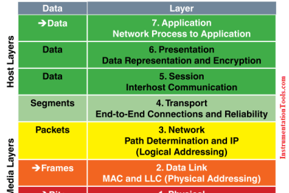
What is the OSI Model?
The Open Systems Interconnect (OSI) reference model is the ISO (International Standards Organization) structure for the “ideal” network architecture. This Model outlines seven areas, or layers, for the network. These layers are (from highest to lowest):
7. Application : Where the user applications software lies. Such issues as file access and transfer, virtual terminal emulation, interprocess communication and the like are handled here.
6. Presentation : Differences in data representation are dealt with at this level. For example, UNIX-style line endings (CR only) might be converted to MS-DOS style (CRLF), or EBCIDIC to ASCII character sets.
5. Session : Communications between applications across a net- work is controlled at the session layer. Testing for out-of-sequence packets and handling two-way communication are handled here.
4. Transport : Makes sure the lower three layers are doing their job correctly, and provides a transparent, logical data stream between the end user and the network service s/he is using. This is the lower layer that provides local user services.
3. Network : This layer makes certain that a packet sent from one device to another actually gets there in a reasonable period of time. Routing and flow control are performed here. This is the lowest layer of the OSI model that can remain ignorant of the physical network.
2. Data Link : This layer deals with getting data packets on and off the wire, error detection and correction and retransmission. This layer is generally broken into two sub-layers: The LLC (Logical Link Control) on the upper half, which does the error checking, and the MAC (Medium Access Control) on the lower half, which deals with getting the data on and off the wire.
1. Physical : The nuts and bolts layer. Here is where the cable, connector and signaling specifications are defined.
What is CSMA/CD?
CSMA/CD is the media access control mechanism used by Ethernet and 802.3 networks; in other words, it determines how a packet of data is placed on the wire.
CSMA/CD stands for “Carrier Sense Multiple Access, with Collision Detection”. Before an Ethernet device puts a packet “on the wire”, it listens to find if another device is already transmitting.
Once the device finds the wire is clear, it starts sending the packet while also listening to hear if another device started sending at the same time (which is called a collision).
What does CRC mean?
Cyclical Redundancy Check – A method of detecting errors in a message by performing a mathematical calculation on the bits in the message and then sending the results of the calculation along with the message.
The receiving work-station performs the same calculation on the message data as it receives it and then checks the results against those transmitted at the end of the message. If the results don’t match, the receiving end asks the sending end to send again.
Ethernet Terms
Aging – function in a switch to update data – especially the address table
ARP – Address Resolution Protocol – used to map an IP address with a MAC address
AARP – an organization to which the owners of ED belong
Auto negotiation – detects at a port the transmission parameters of the connected device
Bandwidth – measurement of the amount of data transmitted in one second – Speed
BMOC – big man on campus – the guys you hated in college
BOOTP – Bootstrap Protocol – delivers an assigned IP address to a specific MAC address
Bush – can be the best thing or, the worst thing
Broadcast – data packet that will be sent to all nodes of a network. Cannot cross a router
Chicago Bears – almost 2006 Super Bowl Champions
Combo port – a gigabit port that has 2 connectors – a 10/100/1000TX copper port and an SFP port. Using one disables the other.
CoS – Class of Service – Classifies traffic into categories – high, medium, low
CSMA/CD – Carrier Sense Multiple access Detect – how ethernet works – collision detection
DHCP – Dynamic Host Configuration Protocol – a mechanism for allocating IP addresses
DNS – Domain Name System – translates network nodes into addresses
Dual Homing – Network topology in which a device is connected to the network by way of two independent access points
ED – Ethernet Direct – a company who wants to be your industrial ethernet switch supplier
Ethernet IP – protocol used in industrial applications – for I/O over ethernet
FDX – full duplex – simultaneous transmission and reception
Flow Control – Procedure used when a port is overloaded – the switch sends a message to an end device to stop sending data
FTP – File Transfer Protocol – a layer 5 protocol which runs over TCP to transfer files efficiently
Gbps – gigabits per second
GMRP – GARP Multicast Registration Protocol
Gouged – how you feel when you buy your IE switches from another vendor
HDX – half duplex – Transmission and reception of data – but not simultaneously
HTML – Hypertext Markup Language
HTTP – Hypertext transfer Protocol – used by web browsers to transfer files
HUB – Layer 1 device – transmits to all ports – not used anymore due to switch technology and cost
IGMP – Layer 3 protocol for Multicast control – needed for I/O over ethernet
IGRP – Interior Gateway Routing Protocol – used by routers
IntraVUE – Network management software for the plant floor, graphical format, diagnostics, Auto IP
IP – Internet Protocol – a Layer 3 protocol most widely used today
IP Address – a logical address, assigned by a network manager Layer 2 uses MAC addresses, Layer 3 uses IP addresses
Jitter – a d de dev deviation in sig sig signal t tt ttt timing
Latency – Time difference between the reception and re-transmission of data in, for example, a switch
LED – Light Emitting Diode, or half of Led Zeppelin
MAC – Media Access Control
Management – Administration, configuration and supervision of network components – such as SNMP
Mbps – Megabits per second
MDI / MDI-X – ability to ‘cross over’ TX port connections – ‘crossover’ cables are not needed if a switch has this feature
MIB – Management Information Base – contains a description of the objects and functions of a network device – defined by SNMP
Monsters of the Midway – the 1985 Chicago Bears
Node – a device on the network – PLC, HMI, Drive, etc.
ODVA – Open Device Vendors Association – manages Ethernet/IP network technology and standards for industrial automation
OLE – Object Linking and Embedding – a window technology to transfer different data between devices
OPC – OLE for Process Control – Protocol used to provide a standard method of data exchange between devices
Port Mirroring – The data traffic at one port copied to another port for the purpose of analysis
QoS – Quality of Service – measure of performance for a transmission that reflects its availability
Repeater – a Layer 1 device that regenerates a signal – all switches act as repeaters
RMON – Remote Monitoring – Defined by SNMP, a method of capturing switch data
Router – a Layer 3 device that connects networks by choosing the best path
SNMP – Simple Network Management Protocol – used to monitor and control network devices – configurations, security, performance
Spanning Tree – Protocol which allows redundant paths – too slow for industrial ethernet – recovery time is > 30 seconds
Store & Forward – a switching mechanism to buffer and transmit packets of data
STP – shielded twisted pair
Switch – Layer 2 device that forwards data to the port where the destination device is connected
TLA – Three Letter Acronym
TCP – Transmission Control protocol – Connection oriented transport protocol on Layer 4 of the TCP/IP protocol stack
TCP/IP – Transmission Control Protocol/Internet Protocol – most widely used from Layer 3 upwards
ToS – Type of Service – Field in the IP packet for prioritization
UDP – User Datagram Protocol – connectionless transport protocol on Layer 4 of the TCP/IP protocol stack
Unicast – data packets that are addressed to only a single device
UTP – Unshielded twisted pair – cable with no shield
VLAN – Virtual LAN, built with switches. A way to restrict broadcasts to the part of the network where they are required
VPN – Virtual Private Network – enables IP traffic to travel securely over a public TCP/IP network by using encryption
Wireless – no wires
W.I.U. – the Harvard of the Midwest in Macomb, IL
WKRP – a radio station in Cincinnati
WLAN – Wireless Local Area Network
Source : ethernetdirect
Articles You May Also Like to Read :
-
Industrial Networking & Wireless Interview Questions
-
What is Foundation Fieldbus (FF) ?
-
PLC Program using Timers
-
How to make RJ45 cable