Inst ToolsInst ToolsInst Tools
  • Courses
  • Automation
    • PLC
    • Control System
    • Safety System
    • Communication
    • Fire & Gas System
  • Instrumentation
    • Design
    • Pressure
    • Temperature
    • Flow
    • Level
    • Vibration
    • Analyzer
    • Control Valve
    • Switch
    • Calibration
    • Erection & Commissioning
  • Interview
    • Instrumentation
    • Electrical
    • Electronics
    • Practical
  • Q&A
    • Instrumentation
    • Control System
    • Electrical
    • Electronics
    • Analog Electronics
    • Digital Electronics
    • Power Electronics
    • Microprocessor
  • Request
Search
  • Books
  • Software
  • Projects
  • Process
  • Tools
  • Basics
  • Formula
  • Power Plant
  • Root Cause Analysis
  • Electrical Basics
  • Animation
  • Standards
  • 4-20 mA Course
  • Siemens PLC Course
Reading: Pitot Tube Problems and Troubleshooting Steps – Flow Instrument
Share
Notification Show More
Font ResizerAa
Inst ToolsInst Tools
Font ResizerAa
  • Courses
  • Design
  • PLC
  • Interview
  • Control System
Search
  • Courses
  • Automation
    • PLC
    • Control System
    • Safety System
    • Communication
    • Fire & Gas System
  • Instrumentation
    • Design
    • Pressure
    • Temperature
    • Flow
    • Level
    • Vibration
    • Analyzer
    • Control Valve
    • Switch
    • Calibration
    • Erection & Commissioning
  • Interview
    • Instrumentation
    • Electrical
    • Electronics
    • Practical
  • Q&A
    • Instrumentation
    • Control System
    • Electrical
    • Electronics
    • Analog Electronics
    • Digital Electronics
    • Power Electronics
    • Microprocessor
  • Request
Follow US
All rights reserved. Reproduction in whole or in part without written permission is prohibited.
Inst Tools > Blog > Flow Measurement > Pitot Tube Problems and Troubleshooting Steps – Flow Instrument

Pitot Tube Problems and Troubleshooting Steps – Flow Instrument

Learn the problems and troubleshooting steps for a DP transmitter with a primary sensor element like a pitot tube or averaging flow meter.

Last updated: February 21, 2023 3:00 pm
Editorial Staff
Flow Measurement
No Comments
Share
5 Min Read
SHARE

Learn the problems and troubleshooting steps for a DP transmitter with a primary sensor element like a pitot tube or averaging flow meter.

Pitot Tube Problems and Troubleshooting Steps

Averaging Pitot Tubes
Image Courtesy: HMA Group

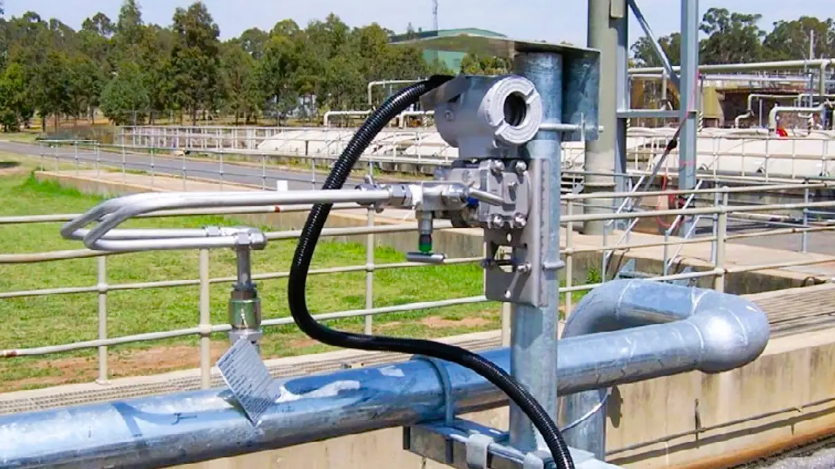
Below mentioned steps will help you to troubleshoot the problems which we might encounter while using a pitot tube.

  1. The first step is to check the DP type transmitter which is used to convert the DP measured by the Pitot tube or Averaging Pitot tube to a suitable signal like 4 mA to 20 mA or FF signal. Check whether the transmitter is in power ON condition or not. If the transmitter is in off condition, then check the supply voltage. If the supply voltage is not present, then check the fuse as well as the barrier in the marshalling cabinet. If the fuse is blown, then replace the fuse (generally the fuse can be found in a 24 V loop power). If the barrier is faulty, then replace the barrier.
  2. If the transmitter is found okay in the Field, but the value mismatches with the control system, then check the configured ranges on the field as well as the system. Confirm ranges as per the Datasheet or any other approved documents. 
  3. Either field or system should have the square root functionality.  If both side square root is present, then the flow value will be incorrect.
  4. If the value is constant in the control system, then check if the value is forced from the PLC or DCS, or ESD systems. Also, check for the field transmitter also. Force can be on the field side also. Remove the force if present after knowing the reason why the transmitter was forced (this option will be available in limited models). 
  5. Check the manifold valve and all intermediate valves for isolation. All should be open. In the manifold, the equalization valve, as well as the vent valve should be closed.
  6. If the flow value is not proper, then try flushing the transmitter impulse lines. Generally, Pitot/Averaging Pitot tubes are used in water services. So, flush them directly. If any other hazardous service is present, then take appropriate precautions for flushing. 
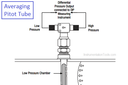
  7. If the values are negative, then check whether the LP side of the transmitter is connected to the LP tapping of the Pitot/Averaging Pitot tube or not and whether the HP side of the transmitter is connected to the HP side of the Pitot/Averaging Pitot tube or not. If found swapped, then correct them after proper isolation.
  8. Check the pressure difference on the HP as well as the LP side of the Pitot/Averaging tube. Use a well-calibrated differential pressure gauge or use a digital gauge to measure both HP side and LP side pressure. If any side’s pressure is doubtful, flush that side again for a few minutes. 
  9. If flushing doesn’t work, then if the process fluid’s pressure is less than Instrument Air pressure, then use Instrument Air to back flush. Back flushing should be done with appropriate material only.
  10. If flow values still are not proper, then remove the Pitot/Averaging tube from the line. For this step, isolation of the line is required.
  11. After removing the Pitot/Averaging tube, inspect the physical condition of the Pitot/Averaging tube. All holes for sensing the pressure in the HP as well as the LP side should be clear. Use pressurized fluid or air to check the condition of the holes. Clean then if any of them is found choked.
  12. Inspect the condition of the vent plug given at the bottom of the Pitot/Averaging tube. If found damaged, then replace it. If found loose, then do proper tightening.       
Pitot Tube Problems and Troubleshooting Steps
Image Courtesy: Abb
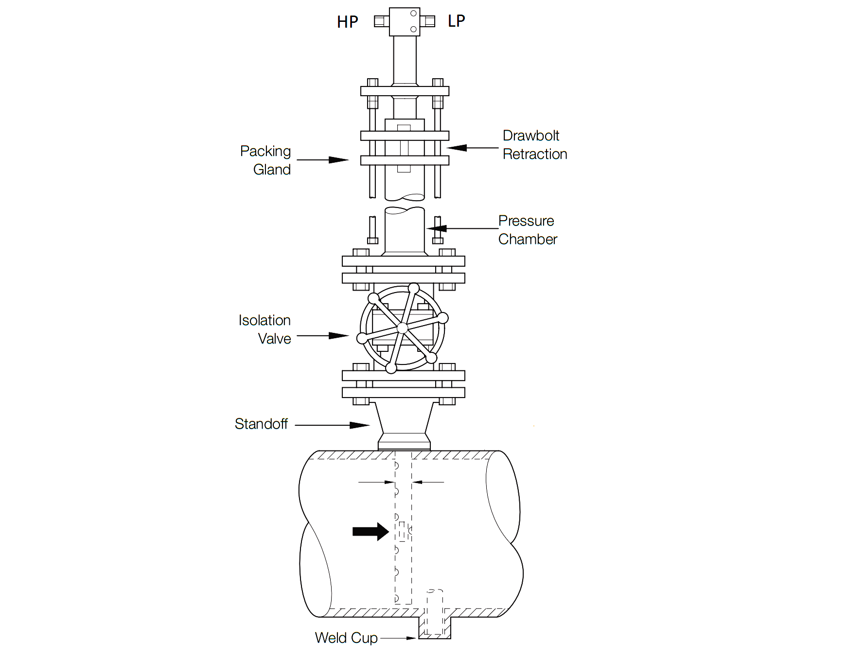
  • If the Pitot/Averaging tube is vibrating while inline, then try to push the Pitot/Averaging tube inside so that the Pitot/Averaging tube sits properly in the Weld Cup.
  • If there is leakage from the gland packing, then tighten the gland.

Read Next:

  • Electrical Heat Tracing
  • Orifice Plate Design Rules
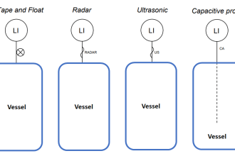
  • Design of Level Gauges
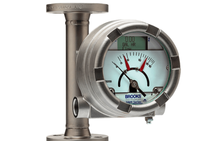
  • Variable Area Flow Meter
  • All About Turbine Meter
Don't Miss Our Updates
Be the first to get exclusive content straight to your email.
We promise not to spam you. You can unsubscribe at any time.
Invalid email address
You've successfully subscribed !

Continue Reading

Mass Flow Meters
Configure the Instruments in Flow Control Loop
Design Considerations of Orifice Plate
Flow Standards
Orifice Flowmeter Rangeability
Annubar Flow Meter – Principle, Advantages, Disadvantages
Share This Article
Facebook Whatsapp Whatsapp LinkedIn Copy Link
Share
Leave a Comment

Leave a Reply Cancel reply

Your email address will not be published. Required fields are marked *

Stay Connected

128.3kFollowersLike
69.1kFollowersFollow
210kSubscribersSubscribe
38kFollowersFollow

Categories

Explore More

Types of Vortex Flow Meter Sensors
Pitot Tube Working Principle
Factors Affecting the Performance of Ultrasonic Flow Meters
Basics of Restriction Orifice (RO) – Types, Applications, Standards
Types of Flow Meters
Troubleshooting Ultrasonic Flow Meter Common Problems
Troubleshooting DP type Transmitter Common Problems
Turbine Flow Meter Coefficient and Scaling Factor

Keep Learning

Flow Switch Principle

In-Line Flow Switch Working Principle and Animation

mass flowmeters

What is a Thermal Flow Meter?

Difference between Orifice & Restriction Orifice

Dall Tube Flow Meter Working Principle

Dall Tube Flow Meter – Principle, Advantages, Disadvantages

Turbine Flow Meter Calibration

How to do Turbine Flow Meter Verification?

Transit Time flow meter Theory

Transit Time Flow Meter Principle

Coriolis Flow Meter Inaccuracy

Coriolis Flow Meter Uncertainty and Inaccuracy

flow-meter-accuracy-calculation

Impact of Flow Meter Accuracy

Learn More

Wireless Projects

100 Wireless Projects – Electrical and Electronics Engineering

PLC Stop - Start Circuit

Introduction to PLC Ladder Diagrams

5-valve manifold

Pressure Transmitter Vent fittings

Definitions of Electrical Grounding

Definitions of Electrical Grounding

Quiz on Manual Motor Starters

100 Quiz Questions on Manual Motor Starters

Top 100 Robotic Projects for Engineering Students

Top 100 Robotic Projects for Engineering Students

6.6kV HV Induction motor Protection

Tank Gauging Measurement

Effect of Tank Design on Accuracy of Level Measurement

Menu

  • About
  • Privacy Policy
  • Copyright

Quick Links

  • Learn PLC
  • Helping Hand
  • Part Time Job

YouTube Subscribe

Follow US
All rights reserved. Reproduction in whole or in part without written permission is prohibited.
Welcome Back!

Sign in to your account

Username or Email Address
Password

Lost your password?