Safety Instrumented System (SIS) – By the name it refers to protecting the Personnel, Plant Equipment, and Environment. In the process industry, SIS handles various hydrocarbons, Oil & Gas, or Nuclear Power plant installations.
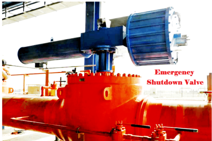
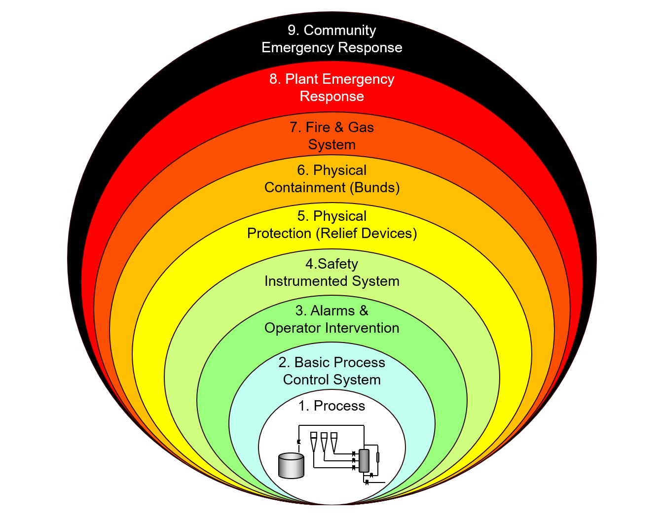
The SIS layer acts as a Protection layer above the Process control layer (viz. DCS). In the event of any hazardous events happening in the plant, SIS acts by using high performance/fast-acting Emergency Shutdown System to contain the hazard.
Various International Standards such as IEC, ISA & ANSI govern the requirements of SIS design.
Safety Instrumented System
SIS is an instrumented protection layer that is designed to move the process to a safe state.
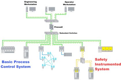
SIS system comprises of – Sensor, Logic solver & Final control element.
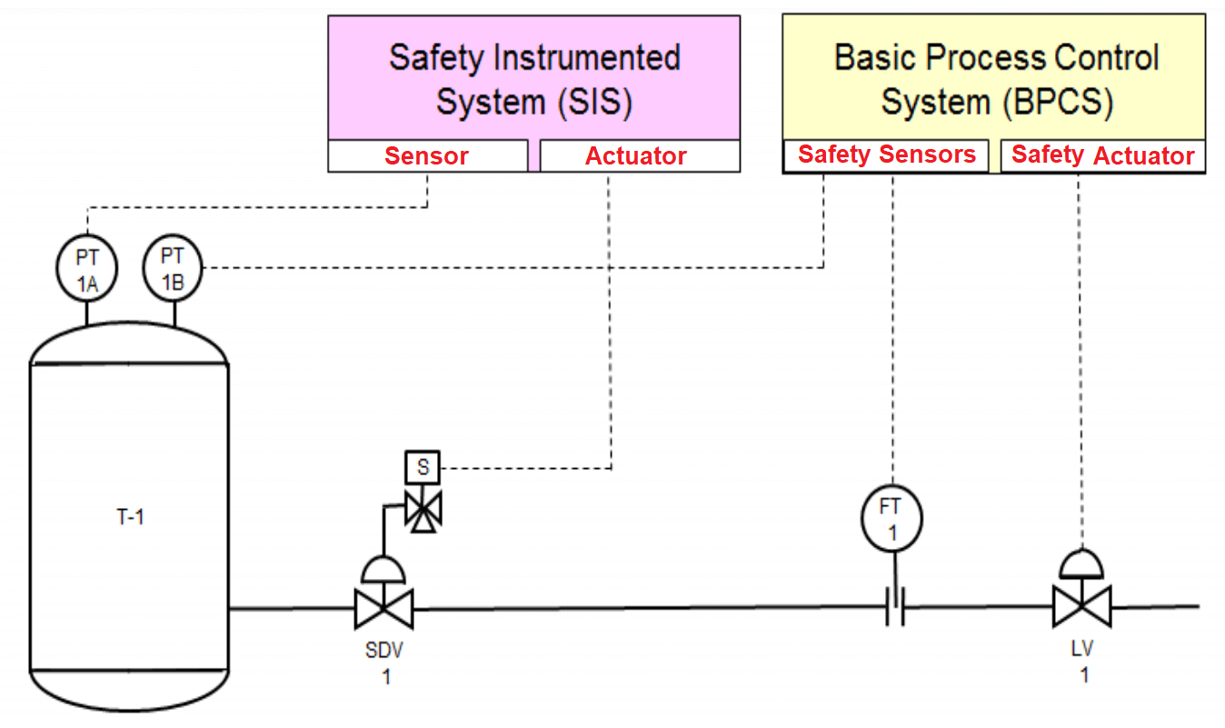
Sensor
An instrument that measures process conditions. Sensor devices that measure temperature, pressure, flow, liquid level, etc.
Logic Solver
An intelligent device that performs logic functions to convert sensor input into an action command to be carried out by the final element.
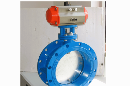
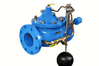
Final Control Element
An equipment that performs the physical action commanded by the logic solver. Final element devices may be control valves, motor/switchgear, etc.
SIS Design Work Process
International Electrotechnical Commission IEC61511 (Functional Safety: Safety Instrumented Systems for the Process Industry Sector) defines the below steps for SIS Design. Many countries have adopted this international standard.
ANSI/ISA-84.00.01-2004.is an alternate standard for IEC, being adopted in a few countries.
| Steps | SIS Work process Description |
|---|---|
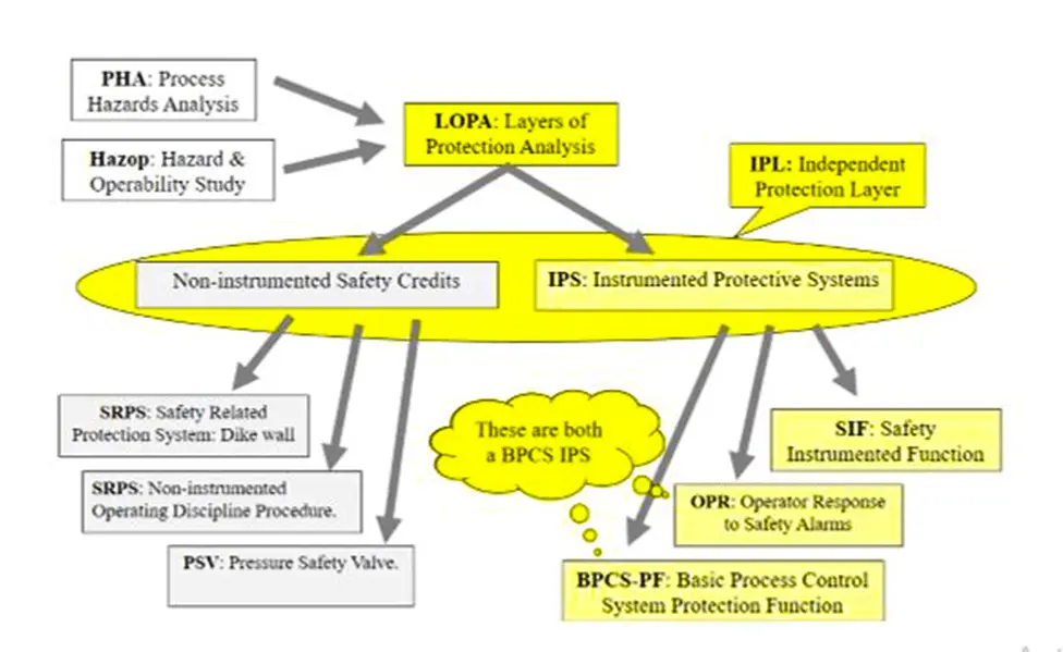
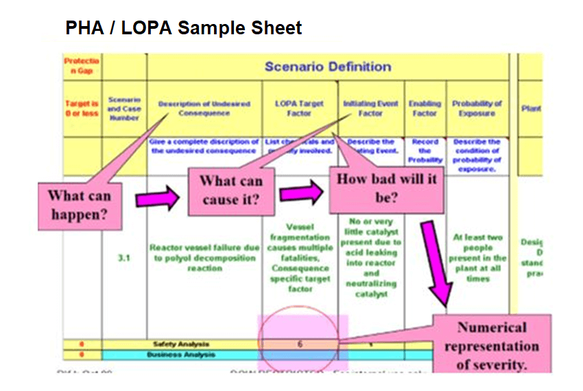
| 1 | Identify and define hazards (PHA/LOPA Study) |
| 2 | Identify and evaluate the highest Risk & target factor scenarios |
| 3 | Perform Risk Analysis and Protection Strategy |
| 4 | Select alternatives protection methodology and document |
| 5 | Define and design the Instrumented Protection System (IPS) |
| 6 | Verify Instrumented Protection System (IPS) design |
| 7 | Develop Instrumented Protection System (IPS) – Operating methods and training |
| 8 | Develop Instrumented Protection System (IPS) Application software |
| 9 | Prepare procedures for Instrumented Protection System (IPS) hardware commissioning |
| 10 | Simulate the Instrumented Protection System (IPS) software & test |
| 11 | Assessment of Instrumented Protection System (IPS) application software and SIS policies with respect to the Area authorities |
| 12 | Validate the Instrumented Protection System (IPS) software and hardware |
| 13 | Register the Instrumented Protection System (IPS) in the ERP system |
| 14 | Operate, maintain, and test Instrumented Protection System (IPS) |
| 15 | Modify the Instrumented Protection System (IPS) |
| 16 | Decommission the Instrumented Protection System (IPS) |
From the above table, we’ll focus on Step.5 – Design SIS
- Different Roles & Responsibilities as per the company standard to be defined (For example Automation system SIS coach, Design engineering lead, Operation Engineer/Leader, Technical center Resource lead, etc).
- Develop conceptual design as per the Safety Instrumented system requirement.
- Review the SIS design (Viz. Sensor configuration, PLC/ESD system design/configuration & Final control element) to ensure that the vendor’s product meets the guidelines prescribed by a Global agency such as Exida or TUV, as below.
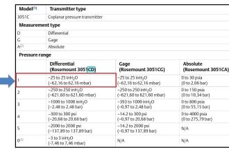
- Instrument Tag
- Instrument Range
- Instrument response time
- Meantime to repair
- Meantime to fail
- Spurious trip rate
- Ensure that the SIS function sensor/Final control element shall work independently without affecting the controls.
- Review the design specifications as per the Safety Instrumented system requirement.
- Develop a conceptual design for SIS Instruments such as “Proof testing”, “Loop verification & validation” requirements.
- Evaluate the design specifications as per the Safety Instrumented system requirement with the Engineering, Operation & Maintenance teams.
- Update the Sensor/Final control element configurations in P&ID (Piping & Instrumentation Diagram).
- Compare the conceptual design with specifications if it’s meeting the SIS requirements. This shall include Proof testing requirements – whether the instrument/valve can be tested online while running the process or any alternate protection instruments in place to protect the people, environment.
- Complete the hardware design, software program coding, etc as per the design specifications.
Contributing factors for SIS design
Management of Change
SIS Design to ensure that Management shall develop policy, strategy, and procedures to implement safety to protect the people and environment.
Each plant shall establish a system for management of change to Safety Instrumented Systems which covers the Design of software and hardware.
Procedures (Operation & Maintenance)
Many written procedures are required for SIS.
- Written procedures shall exist for the plant Safety instrumented system management.
This operating procedure shall include:
- Software program loading,
- Plant – SIS related equipment start-up and shut down
- SIS maintenance.
- Operator Response to Alarms (DCS function)
- Detailed instructions on how to respond to DCS alarms identified in PHA/LOPA
- A standard location for these alarm response instructions needs to be defined by the plant
- Written procedures and access restrictions shall exist for any hardware or software that permits bypass of an SIS or DCS Protection Function.
- Written security procedures shall exist to prevent unauthorized or inadvertent changes to the software (SIS or DCS) program.
- Each plant shall have written procedures to be used in the event of a Safety Instrumented System failure or malfunction.
- Process control code used to activate (SIS or DCS) Protection Function logic shall go through the local management of change procedure.
- A detailed written proof test and validation procedures for each element of the SIS.
- Proof testing shall be executed at intervals defined in the SIF design and must include a visual inspection.
- Validation procedures shall functionally test the entire system during initial validation.
- Correct installations of sensors, Logic solver, DCS/BPCS, and final elements shall be commissioned during Loop check following written loop verification procedures
- Dangerous faults detected by diagnostics or automatic testing, when accounted for in PFD calculation, shall be alarmed, acted upon according to fault tolerance requirements, and have work procedures describing what needs to be done by operations and maintenance.
Independence
The main contributor of a protection layer, in which the performance of a protection layer is not affected by the initiating cause of a hazardous event or by the failure of other protection layers.
Independence ensures that all components of the designed protection layer will not negatively impact each other.
If there are two (2) Independent Protection Layers (viz. DCS, SIS) used in the same case require SIS Design shall consider separate sensors, logic solvers, and final elements.
Software for safety functions shall be independent and separated from software for the Distributed Control System function.
Functionality
Functionality ensures that the operation of the Safety Instrumented Systems matches the requirements defined in PHA/LOPA for the independent protection layers.
Defining the “fail-safe state” of all elements shall be declared in the SIS specifications in order to define the Safety Instrumented Function (SIF)
External influences can create problems, a few examples are mentioned below.
- common wires in a cable tray,
- common operating procedures,
- common maintenance procedures
Integrity
Another factor of a protection layer is related to its ability to perform the specified function under all stated conditions in a specified time.
All Safety Instrumented Systems and properly approved Critical Instrument Systems shall have safety trips programmed as unchangeable constants.
The ability of an instrument to diagnose its own failures is important in designing an effective SIS and assigning an acceptable test frequency
Reliability
This is measured by the Probability of an SIS system, that it will perform correctly under stated conditions for a specified time period or for a specified demand.
Different methods of measurement can maximize the reliability of a redundant system since they minimize common cause failure.
Auditability
Safety Instrumented System reviews for new installations shall be done during the Safety, Health, Environment, hazard conditions related inputs and reviews that are part of the study.
Reviews and Audits of the Safety Instrumented Systems shall be done at least every 5 years.
Access Security
Robust Administrative policies and procedures shall be developed to monitor, control, and audit the SIS system.
As a measure of physical security SIS Design to take care with independent equipment supported by barriers, such as keys, locks, and passwords
Various Terminologies in SIS Design
The below mentioned are different terms used in SIS.
SIL, Safety Integrity Level
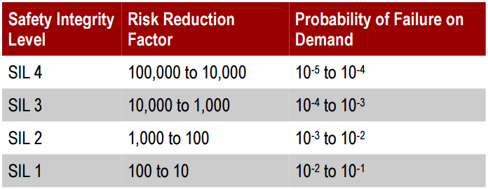
A categorization that represents the average probability of a system being able to satisfactorily perform its required function under all stated conditions within a stated period of time. SIL Level 4 is the highest level and Level 1 is the lowest level on this scale.
- SIL Level 1 means the probability of failure on demand is between 1-in-10 and 1-in-100.
- SIL Level 2 means the probability of failure on demand is between 1-in-100 and 1-in-1,000.
- SIL Level 3 means the probability of failure on demand is between 1-in-1,000 and 1-in-10,000.
- SIL Level 4 means the probability of failure on demand is between 1-in-10,000 and 1-in-100,000.
Probability of Failure on Demand (PFD)
PFD is the probability that a system will fail to perform a specified function on demand.
It shall be equal to (or less than) the target failure measure as specified in the Safety Requirements Specification
Mean Time To Repair (MTTR)
The maximum time a sensor is allowed to continue to operate on a single sensor during repair or test activities.
Proof-Testing
Testing that occurs after start-up as part of routine maintenance.
Written proof-testing procedures specific to that SIS and SIS component define what and how the SIS components are to be tested, as well as specify qualified technical personnel requirements.
Validation Testing
Testing that occurs after construction and before process startup (i.e., Pre-Startup Tests). This testing ensures that the system, as a whole, is operational and performs as intended.
This is a “whole loop” test using the installed field sensors, logic solver computer program, and the actual field equipment including control and mechanical devices (e.g. pumps, generators, etc.).
Conclusion
We’ve gone through the SIS Design concepts, Work process steps, and various contributing factors.
One has to understand, design & implement the SIS components thoroughly with the help of certified SIS professionals. For further understanding of SIS Lifecycle design concepts, various courses are being offered.
Reference:
IEC 61511: “Functional safety – Safety instrumented systems for the process industry sector”