Inst ToolsInst ToolsInst Tools
  • Courses
  • Automation
    • PLC
    • Control System
    • Safety System
    • Communication
    • Fire & Gas System
  • Instrumentation
    • Design
    • Pressure
    • Temperature
    • Flow
    • Level
    • Vibration
    • Analyzer
    • Control Valve
    • Switch
    • Calibration
    • Erection & Commissioning
  • Interview
    • Instrumentation
    • Electrical
    • Electronics
    • Practical
  • Q&A
    • Instrumentation
    • Control System
    • Electrical
    • Electronics
    • Analog Electronics
    • Digital Electronics
    • Power Electronics
    • Microprocessor
  • Request
Search
  • Books
  • Software
  • Projects
  • Process
  • Tools
  • Basics
  • Formula
  • Power Plant
  • Root Cause Analysis
  • Electrical Basics
  • Animation
  • Standards
  • 4-20 mA Course
  • Siemens PLC Course
Reading: Exhaust Fan Control: Example of PLC Timer Programming
Share
Font ResizerAa
Inst ToolsInst Tools
Font ResizerAa
  • Courses
  • Design
  • PLC
  • Interview
  • Control System
Search
  • Courses
  • Automation
    • PLC
    • Control System
    • Safety System
    • Communication
    • Fire & Gas System
  • Instrumentation
    • Design
    • Pressure
    • Temperature
    • Flow
    • Level
    • Vibration
    • Analyzer
    • Control Valve
    • Switch
    • Calibration
    • Erection & Commissioning
  • Interview
    • Instrumentation
    • Electrical
    • Electronics
    • Practical
  • Q&A
    • Instrumentation
    • Control System
    • Electrical
    • Electronics
    • Analog Electronics
    • Digital Electronics
    • Power Electronics
    • Microprocessor
  • Request
Follow US
All rights reserved. Reproduction in whole or in part without written permission is prohibited.
Inst Tools > Blog > PLC Tutorials > Exhaust Fan Control: Example of PLC Timer Programming

Exhaust Fan Control: Example of PLC Timer Programming

When the stove is ON, the exhaust fan control logic will be activated and then remain ON for 1 minute even after the stove is OFF.

Last updated: April 29, 2024 11:18 am
Editorial Staff
PLC Tutorials
1 Comment
Share
6 Min Read
SHARE

This article talks about the simple exhaust fan control logic using the PLC timers.

Contents
Exhaust Fan ControleLearning PLC Training CoursesInputs/OutputsExample of PLC Timer ProgrammingExplanation of ProgramSimulationWhen the Start Button (I0.0) is turned ONWhen the Start Button (I0.0) is turned OFF

Note: This example program is for education purposes and for practicing PLC programming.

Exhaust Fan Control

Problem Statement:

Design a PLC ladder logic for the following application.

We are using one toggle switch to control the Stove and Exhaust Fan.

When the Stove is turned ON, the exhaust fan will be turned ON and it remains ON for 1 minute after the Stove is turned OFF.

eLearning PLC Training Courses

Inst Tools provides free eLearning PLC training courses for engineering students to learn about programmable logic controllers.

PLC Ladder Programming Examples - Exhaust Fan Control

Inputs/Outputs

Digital Inputs:

Start Button: I0.0

Digital Outputs:

Stove: Q0.0

Exhaust Fan: Q0.1

Example of PLC Timer Programming
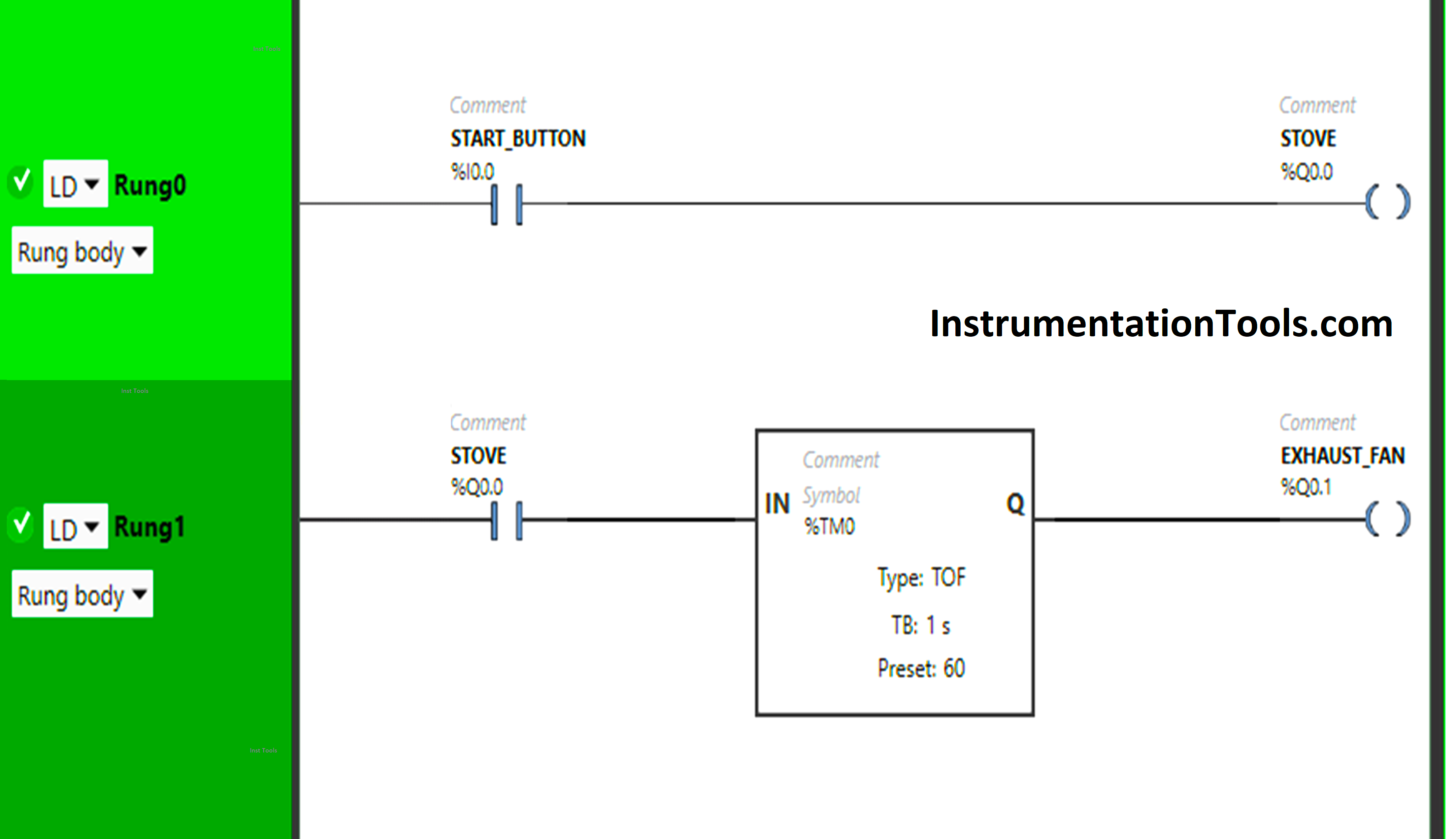
Exhaust Fan Control

Explanation of Program

We have used Normally Open Contact for the Start Button (I0.0) and Stove (Q0.0).

In Rung 0:

  • Normally Open Contact is used for the Start Button (I0.0) to Turn ON the output Stove(Q0.0).

In Rung 1:

  • Normally Open Contact is used for the Stove (Q0.0) to Turn ON the output Exhaust Fan (Q0.1).
  • TOF timer is used to delay the turning OFF time of the output Exhaust Fan (Q0.1) for some time.

So, When the Start Button (I0.0) is turned ON, the output Stove (Q0.0) will turn ON as Normally Open Contact used for the Start Button (I0.0) will be in True State and will pass the signal to the output Stove (Q0.0) and the output stove (Q0.0) will turn ON.
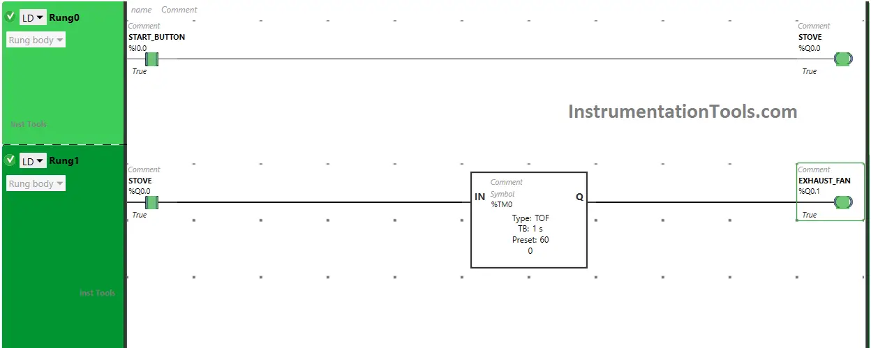
When the output Stove (Q0.0) turns ON in Rung0, Normally Open Contact used for the Stove in Rung1 will be in True State and allow the signal to flow through it and the output (Q0.1) Exhaust Fan will turn ON.

The output Stove (Q0.0) will turn OFF when the Start Button (I0.0) is turned OFF as Normally Open Contact used for the Start Button (I0.0) will be in a false state and does not allow the signal to flow through it.
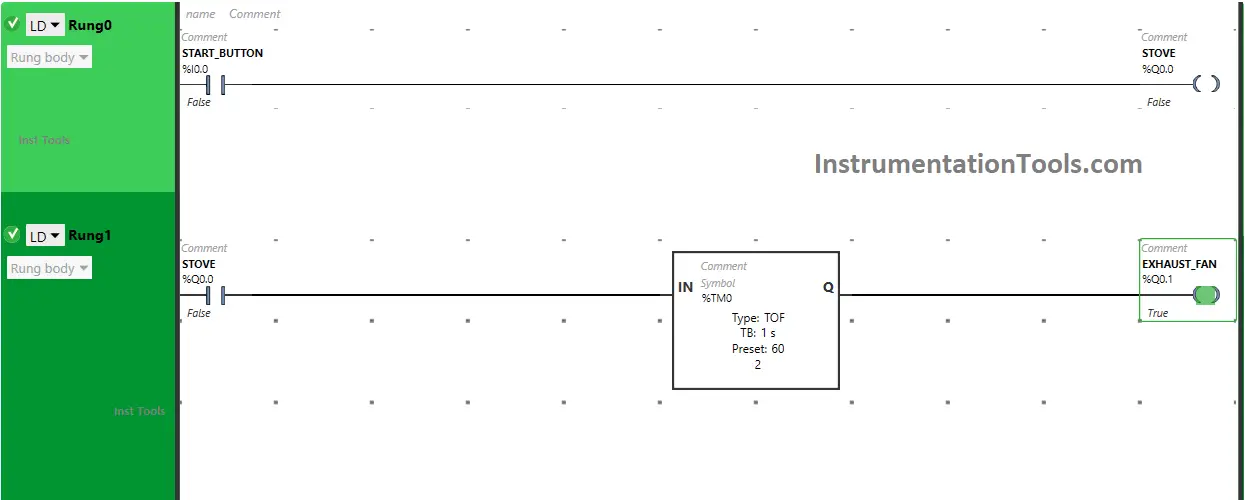
When the output Stove (Q0.0) is turned OFF in Rung0, Normally Open Contact used for the Stove in Rung1 will be in a False State and will not pass the signal to the output Exhaust Fan (Q0.1).
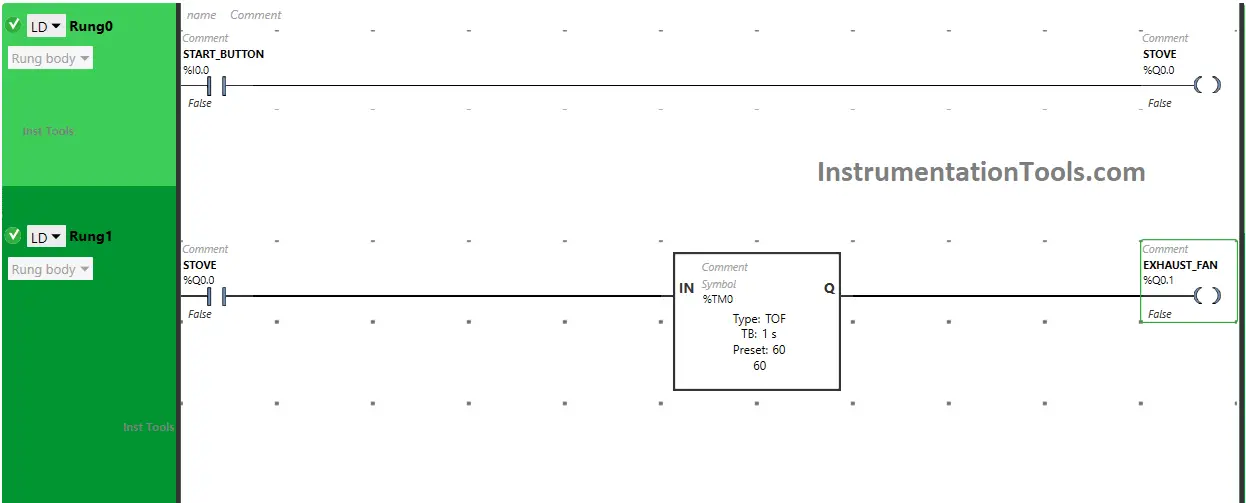
The output Exhaust Fan (Q0.0) will turn OFF but after 60 seconds as the Timer Function Block type TOF is used to delay the turning OFF time of the output Exhaust Fan (Q0.1).

The time is set to 60 seconds. So when the output Stove (Q0.0) turns OFF after 60 seconds the output Exhaust Fan (Q0.1) will turn OFF.

Simulation

Let’s simulate our logic and see the results.

When the Start Button (I0.0) is turned ON

In Rung0, When the Start Button (I0.0) is turned ON, the output Stove (Q0.0) will turn ON as Normally Open Contact used for the Start Button (I0.0) will be in True State and will pass the signal to the output Stove (Q0.0) and the output stove (Q0.0) will turn ON.

Example of PLC Timer Programming

When the output Stove (Q0.0) turns ON in Rung0, Normally Open Contact used for the Stove in Rung1 will be in True State and allow the signal to flow through it and the output (Q0.1) Exhaust Fan will turn ON.

When the Start Button (I0.0) is turned OFF

The output Stove (Q0.0)  will turn OFF when the Start Button (I0.0) is turned OFF as Normally Open Contact used for the Start Button (I0.0) will be in a false state and does not allow the signal to flow through it.

PLC Timer Practice Exercise

When the output Stove (Q0.0) is turned OFF in Rung0, Normally Open Contact used for the Stove in Rung1 will be in a False State and will not pass the signal to the output Exhaust Fan (Q0.1).

When the Start Button (I0.0) is turned OFF

The output Exhaust Fan (Q0.0) will turn OFF but after 60 seconds as the Timer Function Block type TOF is used to delay the turning OFF time of the output Exhaust Fan (Q0.1). The time is set to 60 seconds. So when the output Stove (Q0.0) turns OFF after 60 seconds the output Exhaust Fan (Q0.1) will turn OFF.

If you liked this article, please subscribe to our YouTube Channel for PLC and SCADA video tutorials.

You can also follow us on Facebook and Twitter to receive daily updates.

Read Next:

  • PLC Programming to Control a Pump
  • Manufacturing Line Assembly PLC Logic
  • PLC Ladder Logic Classroom Bell System
  • Batch Mixing PLC Ladder Logic Program
  • PLC Pushbutton and Motor Ladder Logic
Don't Miss Our Updates
Be the first to get exclusive content straight to your email.
We promise not to spam you. You can unsubscribe at any time.
Invalid email address
You've successfully subscribed !

Continue Reading

PLC Code to Start & Stop Motor and Pump as per Logic
PLC Program for Positive Edge Pulse Output for One Scan Cycle
Types of Interrupt OB in Siemens Tia Portal
How to Use ModScan Software for Testing Modbus Communication?
#3 PLC Best Practices – Leave Operational Logic in the PLC wherever feasible
4–20 mA Process Control Loops
Share This Article
Facebook Whatsapp Whatsapp LinkedIn Copy Link
Share
1 Comment
  • Murthy Chidipilli says:
    August 23, 2024 at 11:07 pm

    (%Q0.0) NC contact is false when toggle switch is off. how come the logic flow is maintained through timer to exhaust output(%Q0.1).

    Reply

Leave a Reply Cancel reply

Your email address will not be published. Required fields are marked *

Stay Connected

128.3kFollowersLike
69.1kFollowersFollow
210kSubscribersSubscribe
38kFollowersFollow

Categories

Explore More

Free Download Programmable Logic Controller (PLC) Book
PLC Motor Logic with START, STOP, TEST Push buttons
PLC Program to Control a Water Pump
PLC Programming for Tank Heating Control using Heater
Laws of Boolean Algebra using Ladder Logic
Connecting Blocks in Functional Block Diagram – Studio 5000
Learn about SCADA and HMI Systems
Intrinsically Safe Barriers Questions and Answers

Keep Learning

Conditional Jump instruction

Jump Instruction in Siemens Tia Portal

PLC Program for Food Processing

PLC Program for Food Processing Industry

Real-time PLC Projects

Real-time PLC Projects – Industrial Automation

Tanks Draining Control in PLC using Functional Block Diagram

Tanks Draining Control in PLC using Functional Block Diagram

siemens plc db addressing

FB Block in Siemens PLC Programming

PLC control 4 machines with 1 button

CX-Programmer Tutorial: 1 Button To Activate 4 Different Machines

Controlling of Tank Level Using Proportional Controller in PLC

Controlling of Tank Level Using Proportional Controller in PLC

Omron PLC washing machine automation

Omron PLC Logic for Washing Machine Automation

Learn More

BALL CHECK VALVE THEORY

Types of Check Valves

PLC Raw Count Calculation formula for Pressure Transmitter

PLC Raw Count Calculation for Pressure Transmitter

Lightning Arrester Basics and Terminology

Lightning Arrester Basics and Terminology

Ideal Diode Characteristics Curve

Difference between ideal diode & conventional diode

Digital Electronics Multiple Choice Questions

Characteristics of CMOS Objective Questions

Analog Electronics Objective Questions

Analog Electronics Objective Questions – Set 2

Piping and Instrumentation Diagram

P&ID Guidelines for Separator Vessels

PLC Program using START & STOP Buttons

PLC Program using START and STOP Buttons

Menu

  • About
  • Privacy Policy
  • Copyright

Quick Links

  • Learn PLC
  • Helping Hand
  • Part Time Job

YouTube Subscribe

Follow US
All rights reserved. Reproduction in whole or in part without written permission is prohibited.
Welcome Back!

Sign in to your account

Username or Email Address
Password

Lost your password?