Inst ToolsInst ToolsInst Tools
  • Courses
  • Automation
    • PLC
    • Control System
    • Safety System
    • Communication
    • Fire & Gas System
  • Instrumentation
    • Design
    • Pressure
    • Temperature
    • Flow
    • Level
    • Vibration
    • Analyzer
    • Control Valve
    • Switch
    • Calibration
    • Erection & Commissioning
  • Interview
    • Instrumentation
    • Electrical
    • Electronics
    • Practical
  • Q&A
    • Instrumentation
    • Control System
    • Electrical
    • Electronics
    • Analog Electronics
    • Digital Electronics
    • Power Electronics
    • Microprocessor
  • Request
Search
  • Books
  • Software
  • Projects
  • Process
  • Tools
  • Basics
  • Formula
  • Power Plant
  • Root Cause Analysis
  • Electrical Basics
  • Animation
  • Standards
  • 4-20 mA Course
  • Siemens PLC Course
Reading: Electrical Ladder Diagram Control using Timers Example
Share
Font ResizerAa
Inst ToolsInst Tools
Font ResizerAa
  • Courses
  • Design
  • PLC
  • Interview
  • Control System
Search
  • Courses
  • Automation
    • PLC
    • Control System
    • Safety System
    • Communication
    • Fire & Gas System
  • Instrumentation
    • Design
    • Pressure
    • Temperature
    • Flow
    • Level
    • Vibration
    • Analyzer
    • Control Valve
    • Switch
    • Calibration
    • Erection & Commissioning
  • Interview
    • Instrumentation
    • Electrical
    • Electronics
    • Practical
  • Q&A
    • Instrumentation
    • Control System
    • Electrical
    • Electronics
    • Analog Electronics
    • Digital Electronics
    • Power Electronics
    • Microprocessor
  • Request
Follow US
All rights reserved. Reproduction in whole or in part without written permission is prohibited.
Inst Tools > Blog > PLC Tutorials > Electrical Ladder Diagram Control using Timers Example

Electrical Ladder Diagram Control using Timers Example

In this example program, you will learn the electrical ladder diagram control using timers and toggle switches.

Last updated: April 8, 2024 2:28 pm
Editorial Staff
PLC Tutorials
No Comments
Share
5 Min Read
SHARE

In this example program, you will learn the electrical ladder diagram control using timers and toggle switches.

Contents
Electrical Ladder Diagram ControlPro PLC LearningInputsOutputsLadder Diagram using Timers ExampleProgram DescriptionPLC Program Analysis

Note: The ladder diagram example is prepared to understand the basic programming for electrical engineers.

Electrical Ladder Diagram Control

Problem Statement:

Design a PLC ladder logic for the following application.

We are using one toggle switch to control three motors.

When switch 1 is turned ON,

After 5 seconds, Motor 1 will be ON

After 10 seconds, Motor 2 will be ON

After 15 seconds, Motor 3 will be ON

After 20 seconds, all the motors will be OFF.

Pro PLC Learning

Our PLC learning videos help engineering graduates understand these programs from the basics.

PLC Timer Ladder Diagram - Example Program using Switch and Motors

Inputs

The inputs are listed below.

Switch 1: I0.0

Outputs

The outputs are listed below.

Motor 1: Q0.0

Motor 2: Q0.0

Motor 3: Q0.0

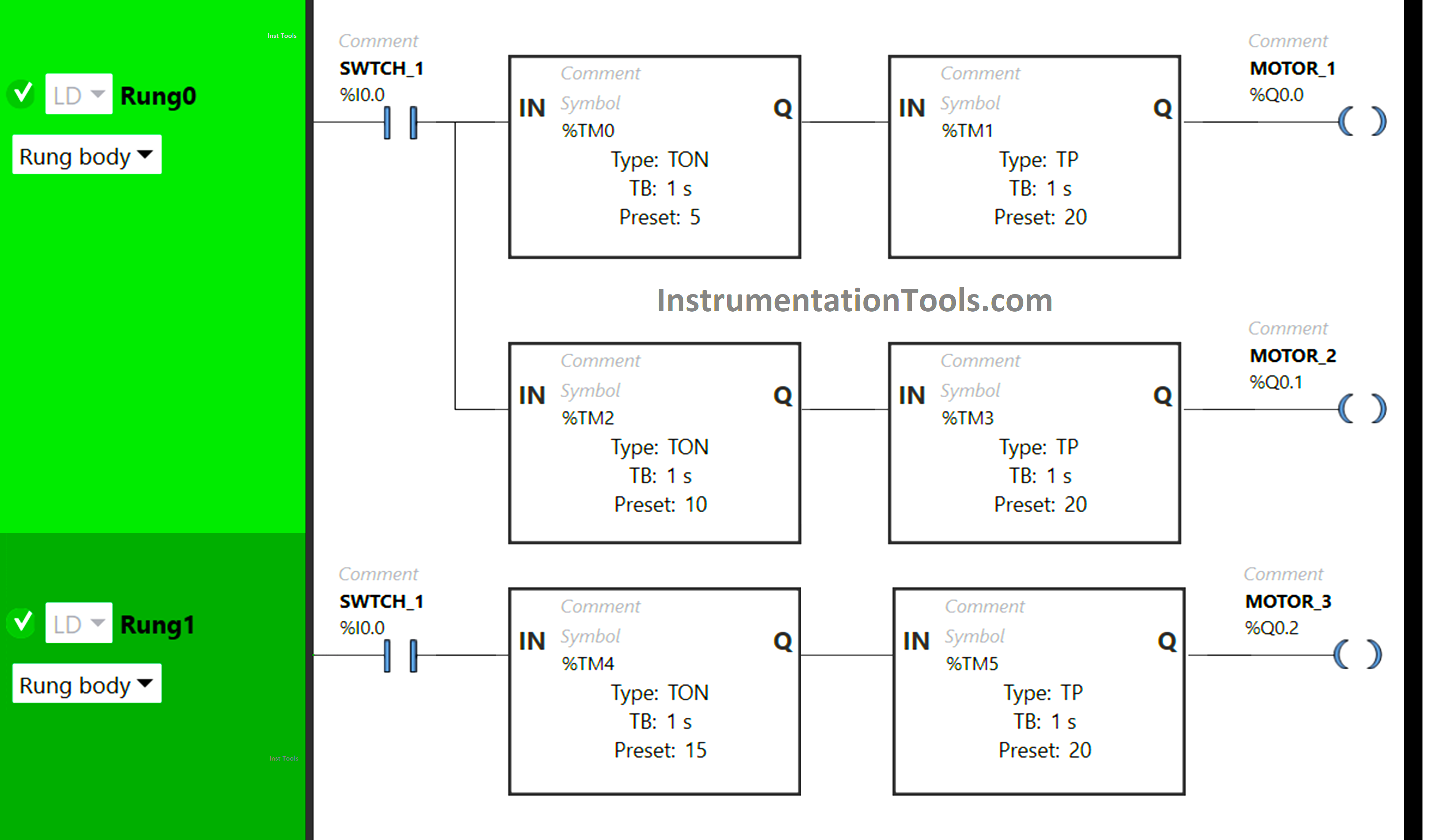
Ladder Diagram using Timers Example
Electrical Ladder Diagram Control using Timers Example

Program Description

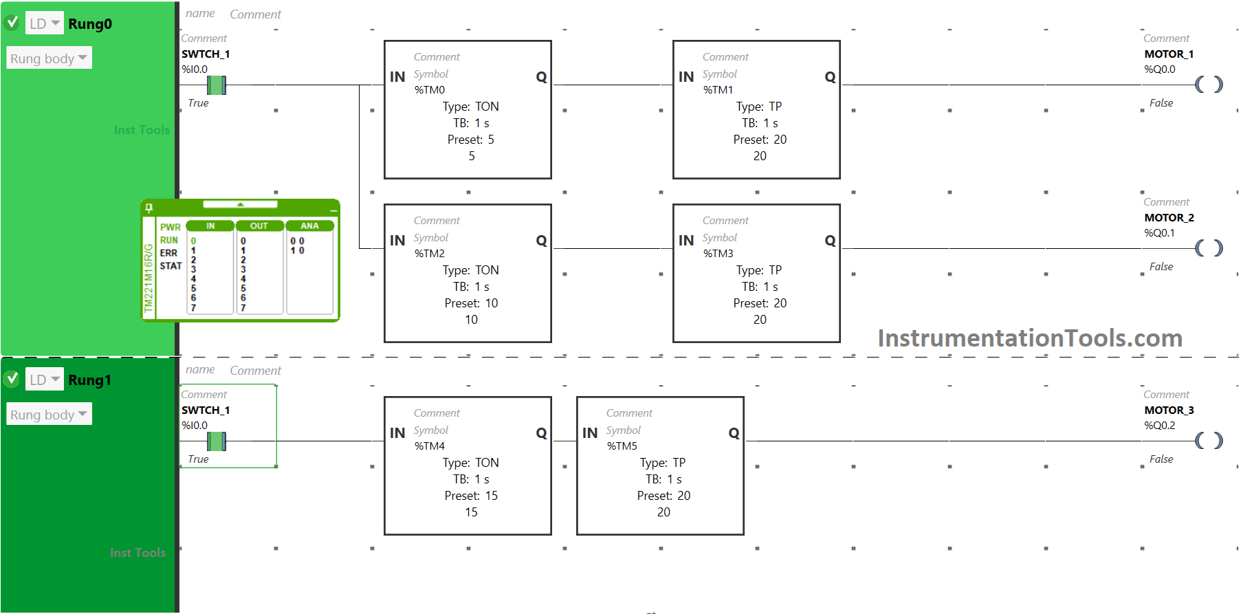
In the PLC program, we have used Normally Open Contact for Switch 1

Two Timer Function Blocks Type TON and TP are used for Motor 1, Motor 2, and Motor 3.

In Rung0:

Normally Open Contact is used for Switch 1.

Timer Function Block type TON is used for Motor 1 to turn it ON after a delay of 5 seconds.

Timer Function Block type TON is also used for Motor 2 to turn it ON after 10 seconds.

Timer Function Block type TP is used to keep Motor 1 ON for 20 seconds.

Timer Function Block type TP is also used for Motor 2 to keep it ON for 20 seconds.

In Rung1:

1) Normally Open Contact is used for Switch 1.

2) Timer Function Block type TON is used for Motor 3 to turn it ON after a delay of 15 seconds.

3) Timer Function Block type TP is also used for Motor 3 to keep it ON for 20 seconds.

PLC Program Analysis
Automation Forum PLC Programming

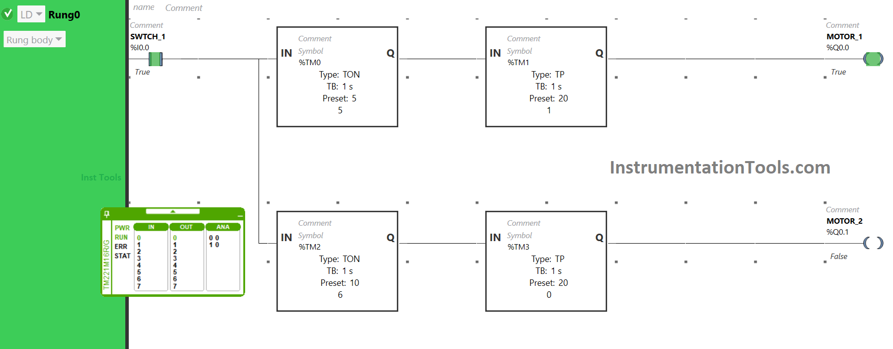
When Switch 1 is turned ON, the Timer functional block type TON (TM0) will allow the signal to flow after a delay of 5 seconds.

After 5 seconds, the signal will flow and the Timer functional block type TP (TM1) will allow the signal to flow for 20 seconds only, and in that duration of time, Motor 1 will be ON.

After 20 seconds, the signal will not flow. As a result, Motor 1 will turn OFF.
Ladder Logic Timer Application

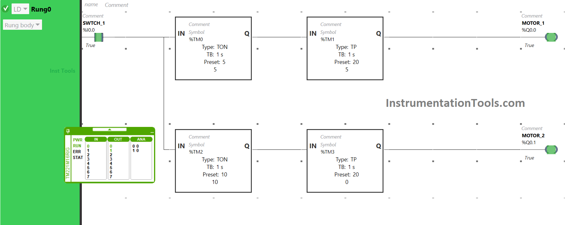
When Switch 1 is turned ON,Ā  after a delay of 10 seconds the Timer functional block type TON (TM2) will allow the signal to flow.

The Timer functional block type TP (TM3) will allow the signal to flow after 10 seconds for 20 seconds only and Motor 2 will be ON for that duration of time only. The signal will not flow after 20 seconds, t. As a result, Motor 2 will turn OFF.
DipsLab PLC

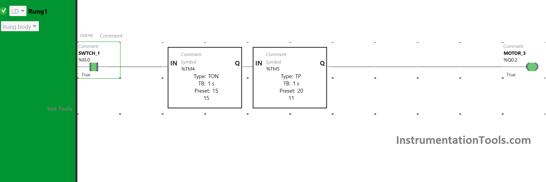
When Switch 1 is turned ON, the Timer Functional Block type TON (TM4) will make it wait for 15 seconds and after that, it will allow the signal to flow.

Then, another Timer Functional Block type TP (TM5) will allow signal only for 20 seconds and Motor 3 will be ON only for that duration of time.

After that, the signal will be blocked and Motor 3 will turn OFF.
PLC Program Analysis

So, When Switch 1 is turned ON, Motor 1 will turn ON after 5 seconds and for 20 seconds, Motor 2 will turn ON after 10 seconds and for 20 seconds and Motor 3 will turn ON after 15 seconds and for 20 seconds.

If you liked this article, please subscribe to our YouTube Channel for PLC and SCADA video tutorials.

You can also follow us on Facebook and Twitter to receive daily updates.

Read Next:

  • From Boolean Algebra to PLC Logic
  • PLC Program for Solenoid & Pilot Lamp
  • PLC Programming Example with Motor
  • PLC to Start or Stop using 1 Switch Program
  • PLC Code to Start & Stop Motor and Pump
Don't Miss Our Updates
Be the first to get exclusive content straight to your email.
We promise not to spam you. You can unsubscribe at any time.
Invalid email address
You've successfully subscribed !

Continue Reading

How Could FB and FC Make Me Professional PLC Programmer?
T-Junction Traffic Control System – PLC Programming
InTouch SCADA Login Password Security
Use of Comments in SCL Language
What Factors Affect the Choice of PLC Programming Software?
DCS Commissioning Steps
Share This Article
Facebook Whatsapp Whatsapp LinkedIn Copy Link
Share
Leave a Comment

Leave a Reply Cancel reply

Your email address will not be published. Required fields are marked *

Stay Connected

128.3kFollowersLike
69.1kFollowersFollow
210kSubscribersSubscribe
38kFollowersFollow

Categories

Explore More

1 to 8 Demultiplexer PLC ladder diagram
Motor Starter Logic using Siemens PLC Tia Portal
Comparison Instructions in PLC Programming
Difference Between SCADA and HMI
Retentive ON Delay Timer using PLC
Glass Cutting and Polishing Machine: PLC Automation Solution
Programmable Logic Controller (PLC) Scan Time – Types, Theory
PLC Mixing Process with Adjustable Timer and Valve Control

Keep Learning

Difference between Power Cables and Signal Cables

Difference between Power Cables and Signal Cables

Classification of Fuses

Step-by-Step Guide to Choose Right Fuse for a Panel

Grounding or Earthing Scheme in DCS or PLC Systems

Grounding or Earthing Scheme in DCS or PLC Systems

plc-analog-signals-wiring-techniques

PLC Analog Signals Wiring Techniques

PLC Program for Car Parking

PLC Program for Entry and Exit Control of Car Parking

Electrical Cabinet Air Conditioner

Electrical Cabinet Air Conditioner – Enclosure Cooling, Maintenance

Siemens PLC Write Protection

How to Protect Siemens PLC using Password?

PLC Automation Memory

What is NOR Flash Memory in PLC?

Learn More

What is FAT and SAT?

What is FAT and SAT? Difference between them

Phase Controlled Half Wave Rectifier RL Load

Power Electronics – Phase Controlled Half Wave Rectifier RL Load

Totally Enclosed Fan Cooled (TEFC) Motor

Totally Enclosed Fan Cooled (TEFC) Motors Rampant Winding Burnouts

Pneumatic Temperature Transmitter with Sensor Principle

Pneumatic Temperature Transmitter with Sensor Principle

PLC TB Wiring

Electrical Signal and Control Wiring

How to Find the Correct Solenoid Valve Size

How to Find the Correct Solenoid Valve Size?

VFD circuit

AC Motor Braking

U-tube Water Manometer

How much Pressure applied to U-tube Water Manometer?

Menu

  • About
  • Privacy Policy
  • Copyright

Quick Links

  • Learn PLC
  • Helping Hand
  • Part Time Job

YouTube Subscribe

Follow US
All rights reserved. Reproduction in whole or in part without written permission is prohibited.
Welcome Back!

Sign in to your account

Username or Email Address
Password

Lost your password?