Industrial automation design involves a lot of tasks from different departments such as electrical, instrumentation, mechanical, and process. Every department needs certain inputs from all other teams then only they can start their work. This raises the need for design documents with detailed information.
Project designing is a hectic job and all the details must be provided in the detailed documentation. This helps every engineer on the team to understand the specific requirements and then they can plan accordingly.
Electrical and Instrumentation Engineering Documents

In this article, we will learn some of the important electrical and instrumentation engineering documents which are necessary to the design & commissioning teams.
In the previous article, we already discussed some of the Pre-engineering documents related to the project & process.
UPS System with Battery Layout
Automation is a very critical process. Any loss in power or any unwanted power disruptions can either damage the equipment or hamper the process. To avoid this, it is necessary to provide a UPS power supply to critical equipment like PLC, PC, or HMI.
When you are finalizing a project, ensure with the customer that they provide a UPS power supply to the electrical panel.
Enquire about UPS backup time, backup current rating, and other battery-related specifications; and make a document on this called – UPS system with battery layout design.
Earthing Layout
Earthing Layout is one of the most important criteria in determining the installation of equipment. Improper earthing can damage the devices. For this, the client provides a document called earthing layout diagram.
It is the duty of the engineer to study it properly before giving the final nod. It has information like fault current distribution modeling, safety calculations, soil resistivity testing, soil modeling and analysis, post-construction audits, stray current studies, and CAD drawings of earthing layouts.
In an electrical panel, power earthing and instrument earthing both are required. So, it must also be ensured that both these earthing will be provided separately by the client.
Electrical Cable Schedule
The Electrical Cable Schedule document will provide information regarding the installation of cables.
Depending on the civil engineering study done and verifying the building floor plan, it provides information regarding length, color, devices at both ends, conduit details, cable type, cable size, cable termination, and routing.
This is very specific in giving accurate details about the cables which will help in final costing, quantity required, and troubleshooting during installation and commissioning.
Electrical Load List
The Electrical Load List document is provided by the customer to help design the electrical panel. It is mostly related to motors, heaters, or other heavy-duty devices.
A 24V DC valve will not consume much current and can be considered in standard current rating. Basically, it provides information regarding feeder type (whether VFD or DOL), working or standby feeder, phase supply, the voltage required, and power rating (in KW). What it does is it will calculate the total KW rating of all the devices.
This will show how much maximum current and power the panel will draw when in working condition. This helps in selecting the bus-bar size, circuit breakers, and fuses for the panel manufacturer.
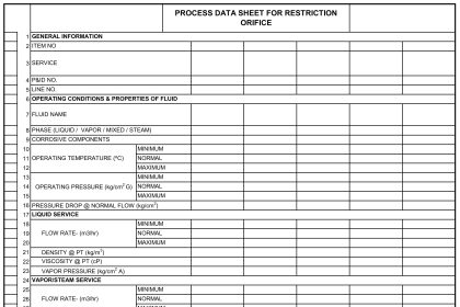
IO List
The IO List document provided by the customer that shows the number of IOs, their tag IDs, analog signal type, and instrument location.
This helps the PLC vendor in designing address wise IO list for the same.
Instrument Index
The Instrument Index document contains the list of instrument devices within a plant that includes the description and complete listing by tag numbers, procurement, and installation information as well as loop drawing number and field installation details.
They can also be further divided into two types for a particular panel – soft and hard. Hard tags are the IOs that will be wired actually with the PLC, and soft tags are the IOs that will be communicated to the PLC via some protocol.
Automation System Architecture
The Automation System Architecture document must be provided by the vendor to show the client’s overall automation system configuration and arrangement.
The system architecture document shows the layout of all the automation devices and their interconnecting networks. This will help in identifying which device is connected where and how it will interface with other devices.
Junction Box Schedule
A junction box (JB) is a housing terminal or slot which allows interconnection between field devices (i.e. instruments, switches, etc.) in the process/production areas, and control or monitoring equipment typically located in the control room. It is located within an electrical panel and allows for wiring field instruments to the internal terminal boards.
This protects the cable from locating itself outside the panel. The cables will go properly from inside the terminal board, to the JB and then outside the panel to the field instrument.
In this way, we understand some of the pre-engineering design documents related to industrial automation (electrical and instrumentation).
If you liked this article, then please subscribe to our YouTube Channel for Instrumentation, Electrical, PLC, and SCADA video tutorials.
You can also follow us on Facebook and Twitter to receive daily updates.
Read Next:
- Instruments Tapping Points
- Junction Box Specification
- Pressure Sensor Specifications
- Selection Criteria of pH Analyzer
- Instrumentation 3D Modeling


Very useful and informative article. Especially electronic earthing is a must for instruments. Shields of instrument-cables should be terminated in electronic-earth without fail.Shield cable to be terminated at one end only(preferably at panel end).