Inst ToolsInst ToolsInst Tools
  • Courses
  • Automation
    • PLC
    • Control System
    • Safety System
    • Communication
    • Fire & Gas System
  • Instrumentation
    • Design
    • Pressure
    • Temperature
    • Flow
    • Level
    • Vibration
    • Analyzer
    • Control Valve
    • Switch
    • Calibration
    • Erection & Commissioning
  • Interview
    • Instrumentation
    • Electrical
    • Electronics
    • Practical
  • Q&A
    • Instrumentation
    • Control System
    • Electrical
    • Electronics
    • Analog Electronics
    • Digital Electronics
    • Power Electronics
    • Microprocessor
  • Request
Search
  • Books
  • Software
  • Projects
  • Process
  • Tools
  • Basics
  • Formula
  • Power Plant
  • Root Cause Analysis
  • Electrical Basics
  • Animation
  • Standards
  • 4-20 mA Course
  • Siemens PLC Course
Reading: How to Test a Pressure Switch ?
Share
Notification Show More
Font ResizerAa
Inst ToolsInst Tools
Font ResizerAa
  • Courses
  • Design
  • PLC
  • Interview
  • Control System
Search
  • Courses
  • Automation
    • PLC
    • Control System
    • Safety System
    • Communication
    • Fire & Gas System
  • Instrumentation
    • Design
    • Pressure
    • Temperature
    • Flow
    • Level
    • Vibration
    • Analyzer
    • Control Valve
    • Switch
    • Calibration
    • Erection & Commissioning
  • Interview
    • Instrumentation
    • Electrical
    • Electronics
    • Practical
  • Q&A
    • Instrumentation
    • Control System
    • Electrical
    • Electronics
    • Analog Electronics
    • Digital Electronics
    • Power Electronics
    • Microprocessor
  • Request
Follow US
All rights reserved. Reproduction in whole or in part without written permission is prohibited.
Inst Tools > Blog > Calibration > How to Test a Pressure Switch ?

How to Test a Pressure Switch ?

Last updated: October 8, 2018 12:15 pm
Editorial Staff
Calibration
5 Comments
Share
2 Min Read
SHARE

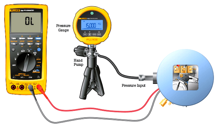
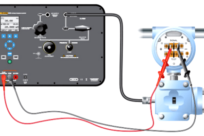
Accurate calibration of pressure switches is a critical step in ensuring process quality and the safe operation of equipment. The setup is similar to pressure gauge calibration except now a voltage or continuity across a set of switch contacts needs to be read either by a (Digital Multimeter) DMM or the calibrator.

The purpose of the calibration is to detect and correct errors in the set point and deadband of the pressure switch. Calibrators can save you time by reducing steps and reducing the amount of equipment you have to bring to the job. With the right calibrator the entire process can be automated.

How to Test a Pressure Switch ?

To perform the test:

Setup

  • 1. Safely disconnect the device from the process it controls.
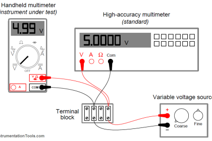
  • 2. Connect the calibrator or DMM to the common and NO (normally open) output terminals of the switch. The DMM or calibrator will measure an “open circuit”. if measuring continuity. If measuring V ac be sure the tool is properly rated for the voltage being measured.
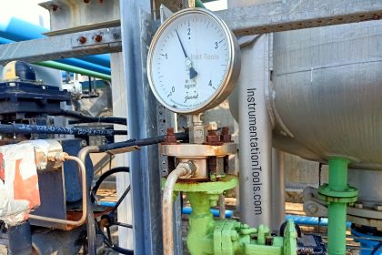
  • 3. Connect the pressure switch to a pressure source such as a hand pump connected to a gauge.

Rising pressure

  • 4. Increase the source pressure to the setpoint of the switch until the switch changes state from open to close. Manually record the pressure value when the DMM indicates a “short circuit” or if using a calibrator it will record the value for you.

Falling pressure

  • 5. Continue to increase the pressure until the maximum rated pressure. Slowly reduce the pressure until the switch changes state again, and resets from closed to open, then record the pressure.

Calculation

  • 6. The setpoint pressure was recorded when the pressure was rising. The deadband value is the difference between the rising setpoint pressure and the falling pressure reset point.

Article Source : Fluke

Don't Miss Our Updates
Be the first to get exclusive content straight to your email.
We promise not to spam you. You can unsubscribe at any time.
Invalid email address
You've successfully subscribed !

Continue Reading

Magnehelic Gauge Calibration
Impulse Line Pressure Testing Procedure
Pressure Transmitter Calibration at the bench
Error sources creating uncertainty in Calibration
Temperature Sensor calibration procedure
Sand Probe Functional Testing
Share This Article
Facebook Whatsapp Whatsapp LinkedIn Copy Link
Share
5 Comments
  • Shanmugam Iyappan says:
    October 15, 2016 at 5:31 am

    Nice instruction for the beginners, Thanks!

    Reply
  • Afrojalam says:
    November 25, 2016 at 1:34 pm

    Easy to understand

    Reply
  • Wisdom Samlafo says:
    December 24, 2016 at 8:51 pm

    Great lecture!

    Reply
  • faijul says:
    January 12, 2017 at 12:46 pm

    very nice

    Reply
  • D A Chowdary says:
    January 19, 2017 at 3:21 am

    Thank u for information sharing..

    Reply

Leave a Reply Cancel reply

Your email address will not be published. Required fields are marked *

Stay Connected

128.3kFollowersLike
69.1kFollowersFollow
210kSubscribersSubscribe
38kFollowersFollow

Categories

Explore More

How to Test a Pressure Gauge
Pig Signalling Switches Functional Testing
Types of Calibration
Bently Nevada Vibration Probes Functional Testing
What is Sensor Trim and Output Trim in Smart Transmitter?
Specific Conductance Calibration Procedure
Calibration : Up-tests and Down-tests
Pressure Gauge Calibration Procedure

Keep Learning

DP Diaphragm Capillary Seal Level instrument

DP Diaphragm Capillary Seal Level instrument Calibration Procedure

Instrument Linearity Error

Instrument Errors – Zero, Span, Linearity

Installation and Calibration of Pressure Transmitter

Installation and Calibration of Pressure Transmitter

Selection of Weighing Balance

Selection of Weighing Balance and Weight for Calibration

Reliability Centered Maintenance (RCM)

What is Reliability Centered Maintenance? (RCM)

Single Position Calibration of Temperature Bath

Single Position Calibration of Temperature Bath

Hydrogen Sulfide Gas Detector Calibration Procedure

Hydrogen Sulfide Gas Detector Calibration Procedure

Displacer Level Transmitter weight calibration

Displacer Level Transmitter Dry Calibration with Weights

Learn More

Vibration Probe Field Setting Procedure

How to do calibration checks of vibration Probe, extension cable and vibration monitor

PLC Pressure Switch Ladder Diagram

Relays in Ladder Logic Tutorials

PID-Controller-Selection

PID Controller Selection

ultrasonic-level-measurement

Ultrasonic Level Transmitter Working Principle

Question on Remote Seal with Capillary Tubing Transmitter

Question on Remote Seal with Capillary Tubing Transmitter

UDT in the PLC Programming

Implement UDT in PLC Programming: User-Defined Data Type

System architecture

Types of System Architecture used in Industrial Automation

VFD Interview Questions and Answers

VFD Interview Questions and Answers – Electrical Drives

Menu

  • About
  • Privacy Policy
  • Copyright

Quick Links

  • Learn PLC
  • Helping Hand
  • Part Time Job

YouTube Subscribe

Follow US
All rights reserved. Reproduction in whole or in part without written permission is prohibited.
Welcome Back!

Sign in to your account

Username or Email Address
Password

Lost your password?