Inst ToolsInst ToolsInst Tools
  • Courses
  • Automation
    • PLC
    • Control System
    • Safety System
    • Communication
    • Fire & Gas System
  • Instrumentation
    • Design
    • Pressure
    • Temperature
    • Flow
    • Level
    • Vibration
    • Analyzer
    • Control Valve
    • Switch
    • Calibration
    • Standards
    • Basics
    • Formula
    • Erection & Commissioning
    • Process Fundamentals
    • Root Cause Analysis
  • Interview
    • Instrumentation
    • Electrical
    • Electronics
    • Practical
  • Q&A
    • Instrumentation
    • Control System
    • Electrical
    • Electronics
    • Analog Electronics
    • Digital Electronics
    • Power Electronics
    • Microprocessor
Search
  • Courses
  • PLC
  • Control Systems
All rights reserved. Reproduction in whole or in part without written permission is prohibited.
Reading: Working Principle of Hydraulic Actuators
Share
Notification Show More
Font ResizerAa
Inst ToolsInst Tools
Font ResizerAa
  • Courses
  • PLC
  • Control Systems
Search
  • Courses
  • Automation
    • PLC
    • Control System
    • Safety System
    • Communication
    • Fire & Gas System
  • Instrumentation
    • Design
    • Pressure
    • Temperature
    • Flow
    • Level
    • Vibration
    • Analyzer
    • Control Valve
    • Switch
    • Calibration
    • Standards
    • Basics
    • Formula
    • Erection & Commissioning
    • Process Fundamentals
    • Root Cause Analysis
  • Interview
    • Instrumentation
    • Electrical
    • Electronics
    • Practical
  • Q&A
    • Instrumentation
    • Control System
    • Electrical
    • Electronics
    • Analog Electronics
    • Digital Electronics
    • Power Electronics
    • Microprocessor
Follow US
All rights reserved. Reproduction in whole or in part without written permission is prohibited.
Inst Tools > Blog > Control Valves > Working Principle of Hydraulic Actuators

Working Principle of Hydraulic Actuators

Last updated: March 21, 2019 4:28 pm
Editorial Staff
Control Valves
No Comments
Share
4 Min Read
SHARE

Hydraulic actuators use liquid pressure rather than instrument air pressure to apply force on the diaphragm to move the valve actuator and then to position valve stem.

Nearly all hydraulic actuator designs use a piston rather than a diaphragm to convert fluid pressure into mechanical force.

The high pressure rating of piston actuators lends itself well to typical hydraulic system pressures, and the lubricating nature of hydraulic oil helps to overcome the characteristic friction of piston-type actuators.

Given the high pressure ratings of most hydraulic pistons, it is possible to generate tremendous actuating forces with a hydraulic actuator, even if the piston area is modest.

For example, an hydraulic pressure of 2000 PSI applied to one side of a 3 inch diameter piston will generate a linear thrust exceeding 14000 pounds (7 tons)!

In addition to the ability of hydraulic actuators to easily generate extremely large forces, they also exhibit very stable positioning owing to the non-compressibility of hydraulic oil.

Unlike pneumatic actuators, where the actuating fluid (air) is “elastic,” the oil inside a hydraulic actuator cylinder does not yield appreciably under stress. If the passage of oil to and from a hydraulic cylinder is blocked by small valves, the actuator will become firmly “locked” into place.

This is an important feature for certain valve-positioning applications where the actuator must firmly hold the valve position in one position.

Some hydraulic actuators contain their own electrically-controlled pumps to provide the fluid power, so the valve is actually controlled by an electric signal.

Other hydraulic actuators rely on a separate fluid power system (pump, reservoir, cooler, hand or solenoid valves, etc.) to provide hydraulic pressure on which to operate.

Hydraulic pressure supply systems, however, tend to be more limited in physical span than pneumatic distribution systems due to the need for thick-walled tubing (to contain the high oil pressure), the need to purge the system of all gas bubbles, and the problem of maintaining a leak-free distribution network.

It is usually not practical to build a hydraulic oil supply and distribution system large enough to cover the entirety of an industrial facility. Another disadvantage of hydraulic systems compared to pneumatic is lack of intrinsic power storage.

Compressed air systems, by virtue of air’s compressibility (elasticity), naturally store energy in any pressurized volumes, and so provide a certain degree of “reserve” power in the event that the main compressor shut down. Hydraulic systems do not naturally exhibit this desirable trait.

Hydraulic Actuators

A hydraulic piston actuator attached to a large shut-off valve (used for on/off control rather than throttling) appears in the next photograph.

Two hydraulic cylinders may be seen above the round valve body, mounted horizontally.

Like the pneumatic piston valve shown earlier, this valve actuator uses a rack-and-pinion mechanism to convert the hydraulic pistons’ linear motion into rotary motion to turn the valve trim:

Hydraulic Actuators

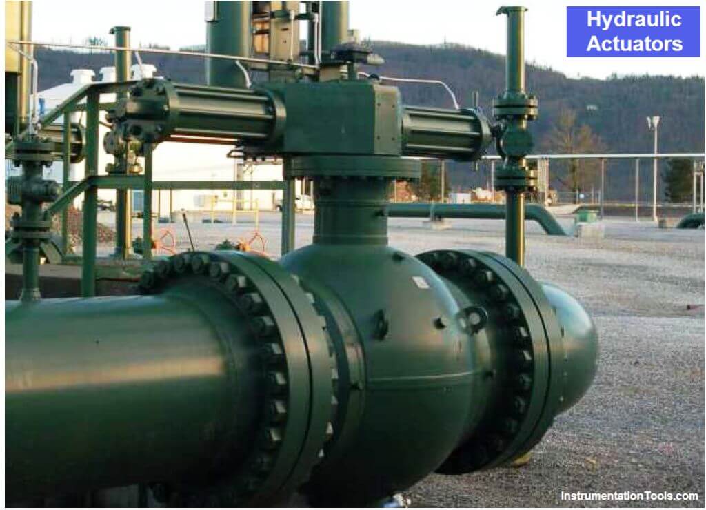
A feature not evident in this photograph is a hydraulic hand pump that may be used to manually actuate the valve in the event of hydraulic system failure.

Also Read : Hydraulic System Questions & Answers

Don't Miss Our Updates
Be the first to get exclusive content straight to your email.
We promise not to spam you. You can unsubscribe at any time.
Invalid email address
You've successfully subscribed !

Continue Reading

Valve Actuator Bench Set
Choke Valve Hydro Testing Procedure
Control Valves Leakage Classifications
Relative Flow Capacity of a Valve
What is Mixing or Diverting Valve ?
Free Control Valve Software Download
Share This Article
Facebook Whatsapp Whatsapp LinkedIn Copy Link
Share
Leave a Comment

Leave a Reply Cancel reply

Your email address will not be published. Required fields are marked *

Stay Connected

128.3kFollowersLike
69.1kFollowersFollow
208kSubscribersSubscribe
38kFollowersFollow

Categories

Explore More

Basics of Globe Valves
Pneumatic Valves Questions & Answers
What is a 4-way Solenoid Valve?
Solenoid Valve with Manual Reset Working Principle
Fundamentals of Valves and their Types
Classification of Solenoid Valves
What is Tilting Disk Check Valve ?
Components of Shutdown Valve

Keep Learning

2-way solenoid valve Normally Closed

What is a 2-way Solenoid Valve ?

Valve Face to Face Dimension

Face to Face Dimension of Control Valve

Air Pressure Regulator cut-away diagram

Air Pressure Regulator Questions

Volume Booster Working Principle

Control Valve Volume Booster Working Principle

Flapper nozzle system

What is Flapper Nozzle System ?

Questions and Answers on Valves

Valve Quiz

Difference between Butterfly Valves and Ball Valves

Difference between Butterfly Valves and Ball Valves

Pinch Valve

What is Pinch Valve ?

Learn More

Transformers Interview Questions & Answers

Measurement and Instrumentation Objective Questions – Part 2

Mass Spectrometer Questions and Answers

Tandem Mass Spectroscopy

How to Prevent Ground Loops in Analog Circuits?

How to Prevent Ground Loops in Analog Circuits?

Negative Readings in Gas Detectors

Why Negative Readings in Gas Detectors ?

Why Calibration is Important

Why Calibration is Important?

3-Wire, Three-Phase Delta Wiring System

3-Wire, Three-Phase Delta Wiring System

Difference Between Modbus and Profibus

Difference Between Modbus and Profibus

Mass Spectrometer Questions and Answers

Quadrupole Mass Spectrometer

Follow US
All rights reserved. Reproduction in whole or in part without written permission is prohibited.
Welcome Back!

Sign in to your account

Username or Email Address
Password

Lost your password?