R.T.D.
Accuracy checks for a resistance temperature detector/device (RTD) is often necessary to validate the accuracy of a new RTD.
How They Work
There are three basic types of RTDs: 2-wire, 3-wire, and 4-wire units all of which are wired in a bridge configured circuit.
An RTD is a metallic element whose resistance varies with temperature. By connecting it in one leg of a Wheatstone bridge, its resistance can be measured.
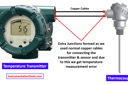
2-wire RTDs are susceptible to errors caused by changes in lead wire resistance.
To compensate for these and other errors, 3-wire RTDs and 4-wire RTDs may be used when accuracy is required.
Input and Output Measurement Standards
The application range of the RTD determines the measurement standards to be used to check this instrument.
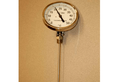
An appropriate input standard would be a temperature bath. A standard thermometer must be placed in one of the wells to confirm the accuracy of the bath.
RTDs do not require temperature compensation. A volt-ohmmeter or decade resistance box can be used as the output measurement standard, because they measure resistance.
To check an RTD with a volt-ohmmeter, look-up tables that relate RTD resistance to temperature are needed.
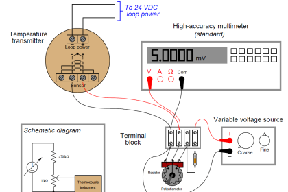
Connections
The two red RTD leads are connected to the positive meter leads, and the black RTD lead is connected to the negative lead.
Three Point Check
Test RTDs at: ambient temperature, mid-range temperature and high end of range temperature. RTD’s cannot be calibrated.
When they are not within the manufactures specifications, the unit must be replaced.
R.T.D. Transmitters
A multifunction temperature calibrator is used to provide all the necessary input values and output measurements.
The calibrator provides the RTD simulation for the transmitter inputs and a milliammeter to measure the transmitter outputs.
RTD tables are not necessary because temperature can be input directly.
Connect the RTD transmitter input and output terminals according to the diagram provided with the calibrator.
The calibrator simulates the RTD resistance for the transmitter and displays the resulting milliamp output.
Perform a five point upscale and downscale test.
Zero is corrected at 10% input and adjusted for 10% output as shown on the milliammeter. Correct the span at 90%.
Zero and span interact, recheck and adjust as required.
Also Read : How 3 wire RTD Lead wire Resistance Eliminated ?


many many thanks to instrument family who is created this type of application