In this section, we will see what is auto cane feed control (ACFC) is, where it is used and how it improves sugar industry Efficiency.
Auto Cane Feed Control System
This is a Control system for feeding the sugarcane in the Sugar Industry. This system is a PLC/DCS based industrial automation system.
The ACFC has a proportionate control Such that the load must be within the safe limits to avoid tripping, Stoppage, and damage of Mill Devices.
The ACFC system is DCS Based System. The Details of the Hardware and Software used are shown below.
- Make : ABB
- Controller : AC 900F
- Software Used : ABB FREELANCE 2016 SP 1
- SCADA /HMI Software : Digivis
The main objectives of ACFC
The main objective of the ACFC system is designed to ensure the safe and uniform feeding of the prepared cane to the mill devices to achieve targeted efficiency and smooth running of the mill by continuous monitoring.
Installing an ACFC system in the plant has some benefits.
- 10% to 15% increase in crushing rate.
- No tripping and stoppage of mills and preparatory devices
- The efficiency can be achieved due to uniform load at all devices.
- Reduces steam and power consumption.
- Pol % bagasse is low. i.e. Improves Extraction
- Low moisture content bagasse %
- Better clarification because juice flow becomes stable.
- Human errors are reduced.
Previously in the olden days (without ACFC system ) the speed of the Main Cane Carrier (MCC) is been regulated manually by operators by continuous monitoring the Cane Blanket level in the Main Cane Carrier (MCC) and Main Rake Carrier (MRC) and the loads on the Cane Preparatory Devices.
Practically it is very difficult to maintain the uniform Cane Blanket level. It results in overloading and tripping.
To overcome this problem the sugar mill is now utilizing the ACFC system.
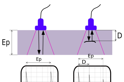
The Cane Blanket level sensor is installed on the Main Cane Carrier (MCC) prior to Cane Preparatory devices. And plays a very important role. This Sensor detects the cane blanket level and sends the signal to the PLC / DCS Such that the load can be controlled by varying the Speed of the Main Cane Carrier.
Donnelly chute control is the overriding control and gets priority over all other signals because the level in the Donnelly chute decides the speed of the MCC and MRC.
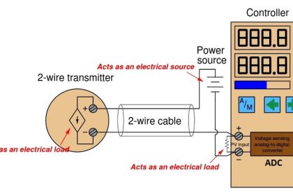
Loads on Cane Preparatory Devices and mill are sensed by Current Transformer in terms of Load Current in case of DC Drives.
The cane feeding in the Main Cane Carrier is controlled in accordance with
- Level on the Main Cane Carrier (MCC)
- The load on all Mills and
- The load on Cane Preparatory Devices.
- Level in the Donnelly Chute.
The Main Cane Carrier speed depends on
- Cane Blanket Level on MCC.
- Load on the main Rake carrier.
- Load on the Cane preparatory devices (Leveller, Chopper and Fibrizer).
- Mill 0 Donnelly chute Level.
- The Current Transformer CT signal of the Cane Preparatory Devices is connected to on-off controller.
- The individual set points (SP) are given (L C F) to the ON/OFF controller.
- If any set point from (L C F) gives OFF signal to proportional controller then it reduces the speed of the corresponding device (Main Cane Carrier) with the help of A/M Switch.
- Every fraction of second the load on the preparatory device is sensed by CT suppose the loads are in decreasing mode speed will increase and vice-versa.
- If it crosses the set point then ON/OFF control take part in control otherwise it is away from the system
The Rake Carrier Speed Depends upon
- Load on Mill
- Speed of Mill
- Raw Juice Tank Level
Working of Main Rake Carrier and Inter Rake Carriers
- According to the crushing rate, the load current on the mill drives varies.
- Speed of the Main Rake Carrier is controlled by sensing the chute level and load current of the Mill.
- Reduced Main Rake carrier speed reduces the speed of all Main Cane Carrier proportionally.
- Main Rake Carrier is not affected by any load variation or Tripping of the Cane Preparatory Devices and the main Cane carrier.
- Tripping of any Inter Rake Carrier (IRC) Trips all the preceding Inter Rake Carriers.
- If the IRC IV gets tripped due to overload then all the IRC III IRC II and IRC I and Main Rake carrier (in my plant).
Controlling Mill Load and Speed using ACFC system
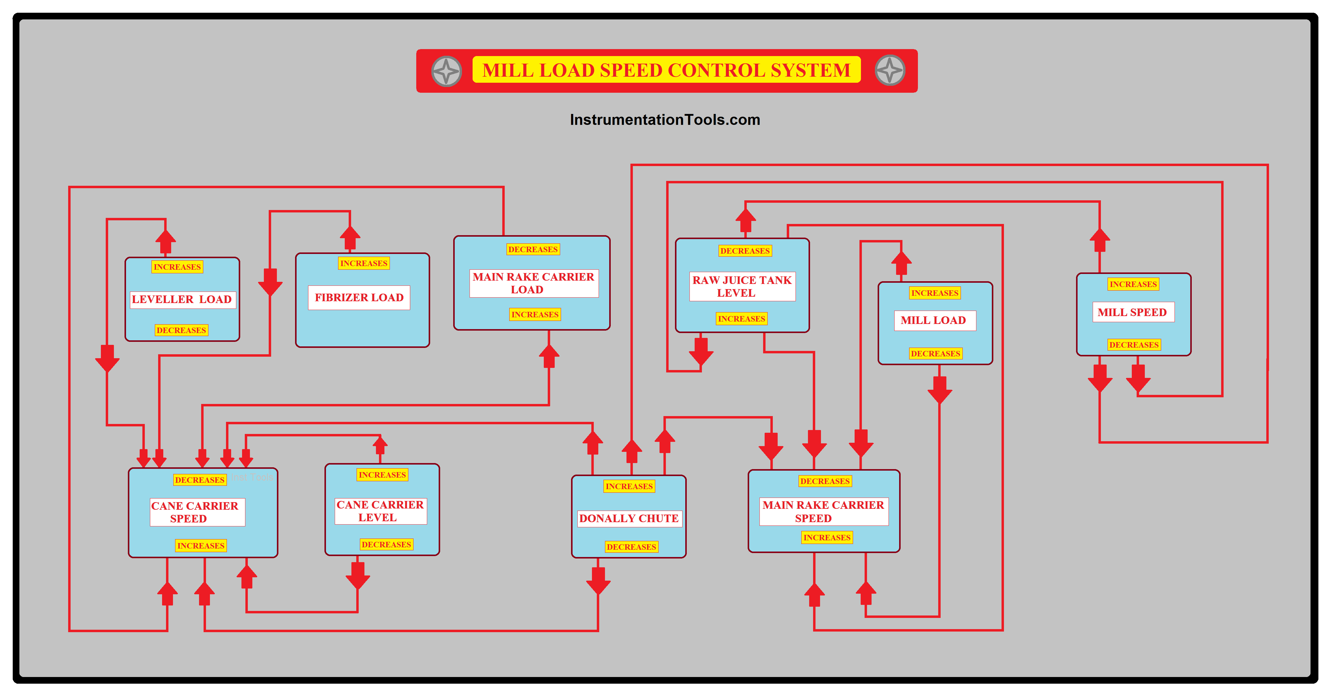
Speed of Main Cane Carrier (MCC)
The speed of MCC depends on the Cane level in MCC and the load on the Cane Preparatory device and Mills.
Controlling the speed of the Main Cane Carrier is very important for the safe operation of the plant.
Usually, for safe Operation, the Range of the Main Cane Carrier Speed is set to 80 % of the Rated RPM.
Speed of MRC and IRC of all mills
The speed of MRC depends upon the Mill 0 chute Level Mill load. The speed of IRC (1-4) depends upon their Mill (1-4) chute Level.
If the mill 0 chute level rises to max level then the main rake carrier speed is reduced. If the Mill (1-4) chute level rises to max level then their IRC speed is reduced.
Raw juice tank Level
The speed of the main Cane carrier and Mill depends on the raw juice tank level.
If the tank level exceeds to maximum level then the mill Speed reduces to the minimum level. The mill speed is inversely proportional to the raw juice tank level.
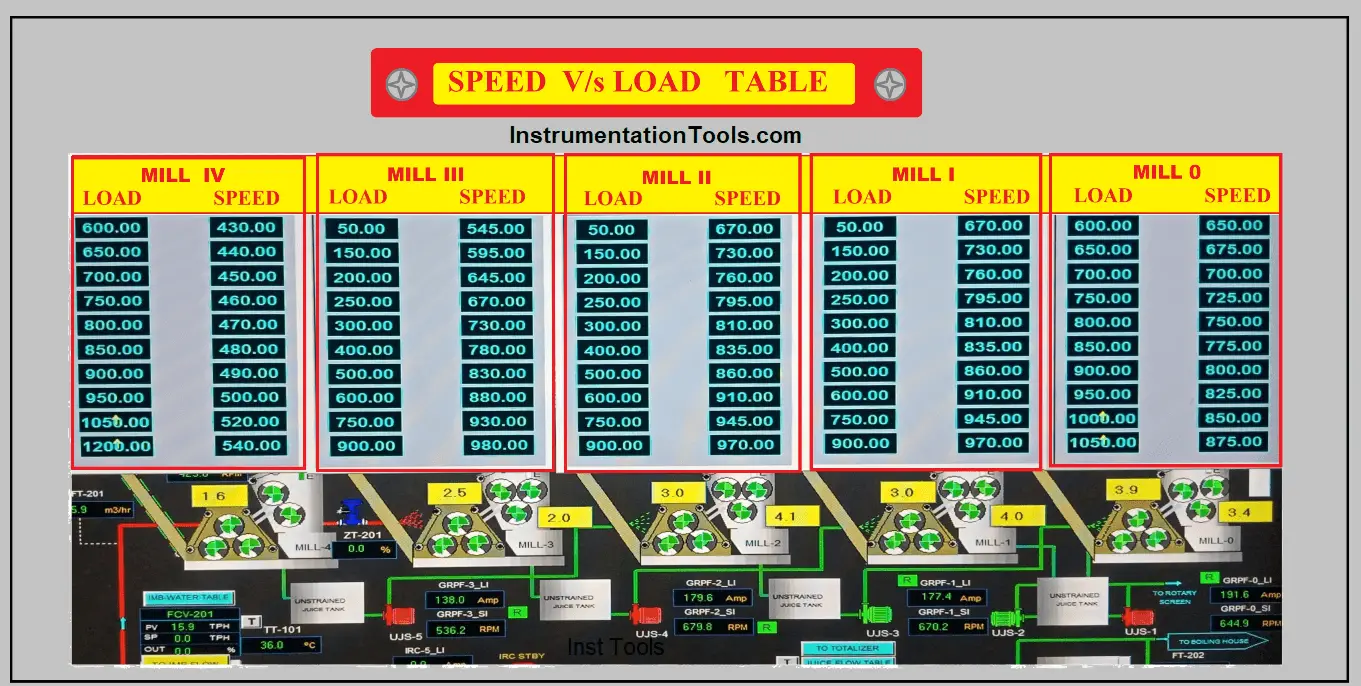
Load on Mill
The loads on all the mills are not equal. And the load on each mill is set in proportion to the mill roller size and its drives.
The load on the last mill (Mill IV in this case) must be higher than about 1200 Amps. Then preceding mills for proper extraction of juice in the mill the load factor is very important to be considered.
The Speed V/s load on the last mill (Mill IV) is different from other mills in order to achieve the complete extraction.
The speed of each mill drive is controlled in proportion to the load on the mill within the preset high and low speeds limits with the objective of maintaining desired loads on devices. The operator needs to raise the speed manually depending upon the rise in load.
The speed V/s Load table of all mills is shown below.
If the load current of the mill drives is more than the setpoint SP i.e. PV > SP then the ON/OFF controller gives the signal to Proportional Controller to control the speed of the Main Rake Carrier and Main Cane Carrier.
In this way, the overall process is continued and uniform cane feeding is given to the mill and hence the load current is maintained on all the drives to achieve the desired efficiency.
Here the load Current is the Independent factor and is inversely proportional to speed.
i.e. If Load Current Increases the speed decreases and vice versa.
The proportional controller of the Mill and Cane Preparatory Devices are interconnected to each other and has ratio control in such a way that if
- The speed of the Main Rake Carrier reduces then speed of the Main Cane Carrier also reduces automatically
- If the Main Rake Carrier trips the Main Cane Carrier will stop immediately.
- If IRC 4 tripps then all the preceding Inter Rake Carrier IRC3 IRC2 and IRC 1 gets stopped immediately.
Level sensors in Donnelly Chute are used to monitor chute level at each mill if the Inter Rake Carrier is provided with Variable Speed Drives and speeds are regulated in direct proportion with respect to Donnelly chute level.
When the level in a particular Donnelly chute rises above an extremely high level even after the mill speed reaches its maximum preset limit then the Inter Rake Carrier of that mill and all the preceding carriers will stop automatically.
One more feedback is taken from the top roller lift sensors overloading on the mill will also be reflected in increased top roller lift hence this is sensed and speed is varied in direct proportion to the top roller lift.
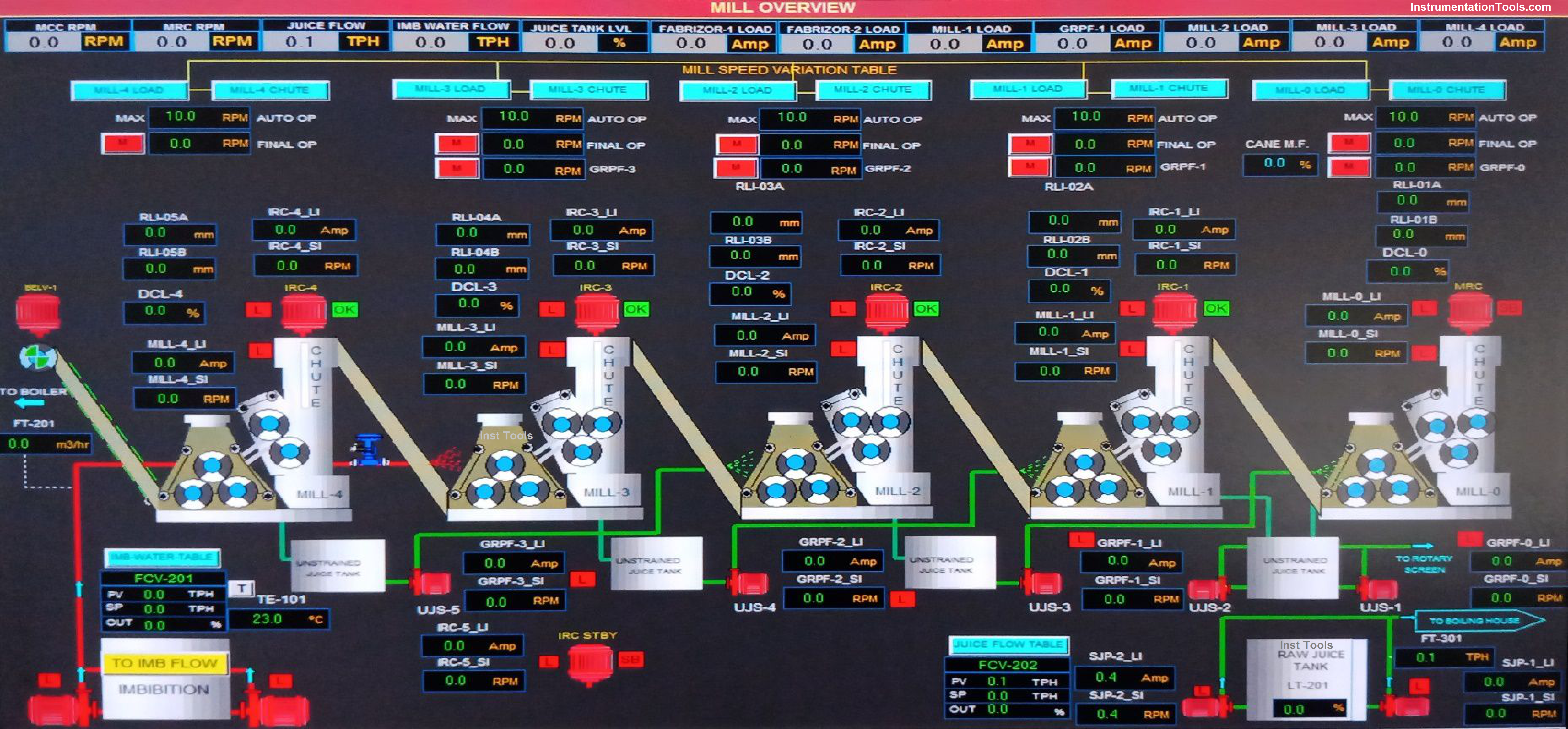
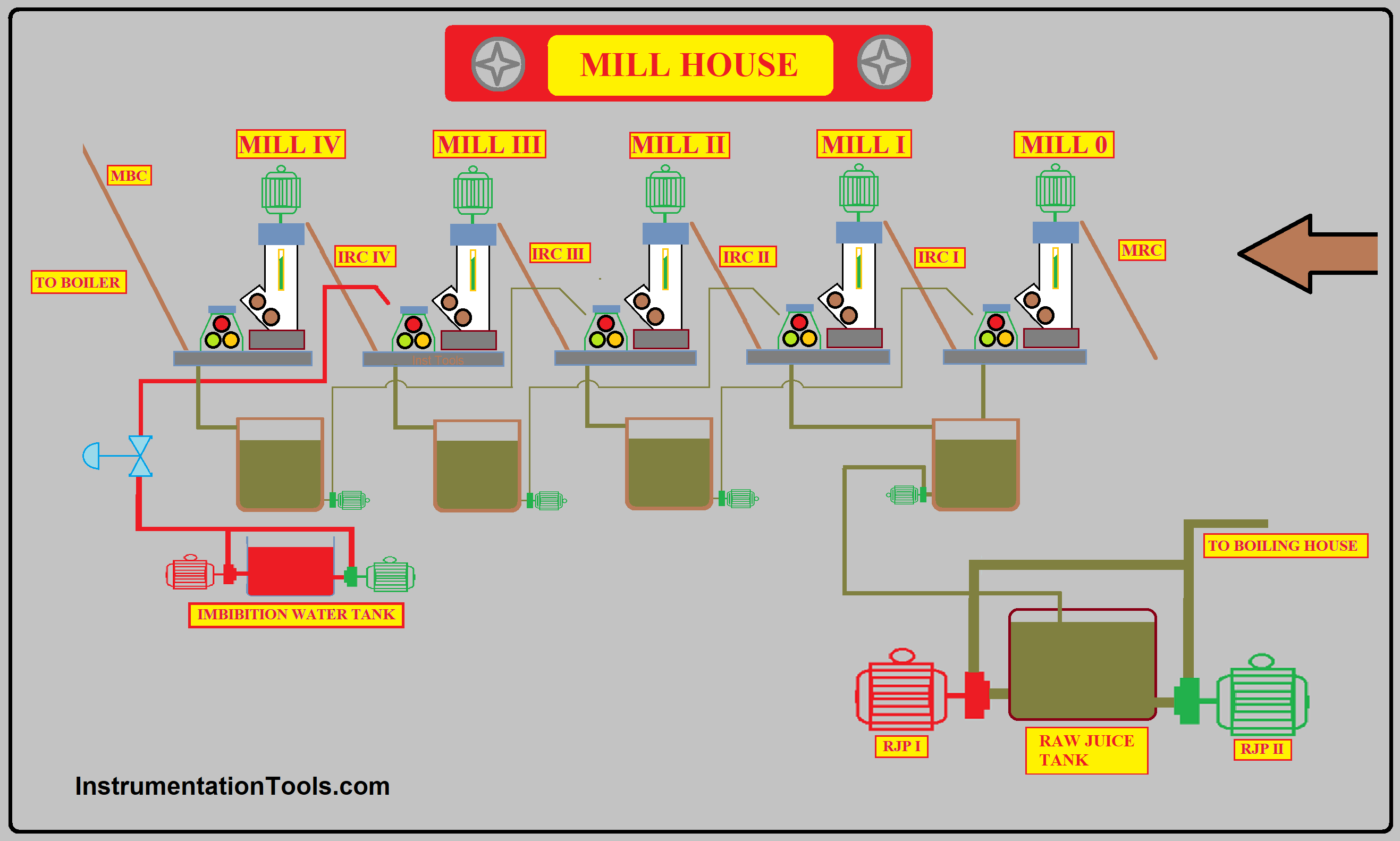
The schematic of the Cane Preparatory Device and Mill House is shown in the figure below.
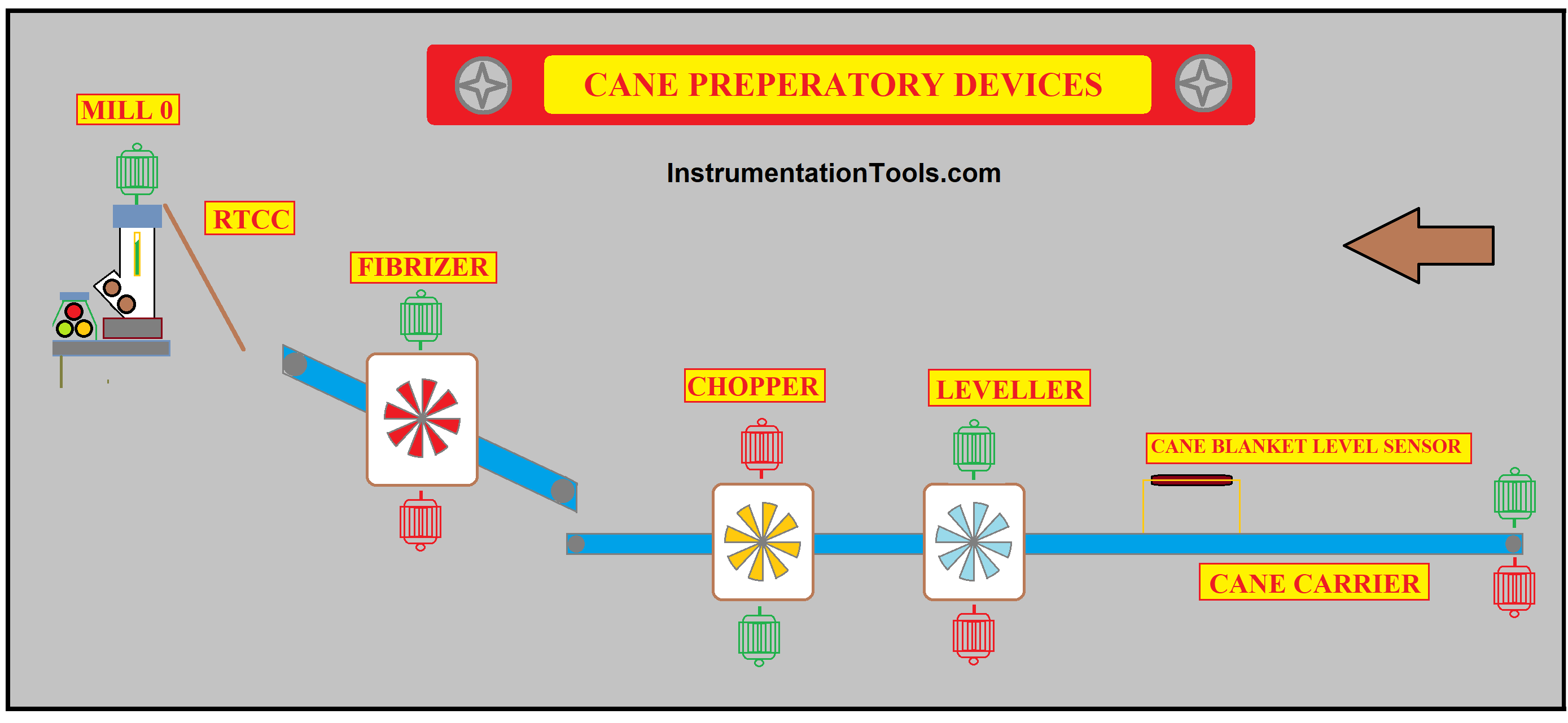
The Arrow mark indicates the direction of the flow of cane in the mill.
What is Cane Preparatory Device?
The preparatory devices are the rotary devices with a set of cutter blades used to prepare the cane by cutting the cane into short pieces to increase the mill Efficiency and mill capacity.
The preparatory devices are Leveller, chopper, and Fibrizer.


what is the price of this system ?
Ex-works factory price in USD and payment terms ?