Instrumentation is the science of automated measurement and control. Applications of this science abound in modern research, industry, and everyday living. From automobile engine control systems to home thermostats to aircraft autopilots to the manufacture of pharmaceutical drugs, power Plants, Oil and Gas, Refineries etc.. and automation surrounds us.
The first step, naturally, is measurement. If we can’t measure something, it is really pointless to try to control it. This “something” usually takes one of the following forms in industry:
- Fluid pressure
- Fluid flow rate
- The temperature of an object
- Fluid volume stored in a vessel
- Chemical concentration
- Machine position, motion, or acceleration
- Physical dimension(s) of an object
- Count (inventory) of objects
- Electrical voltage, current, or resistance etc…
Once we measure the quantity we are interested in, we usually transmit a signal representing this quantity to an PLC/DCS systems where either human ( manual ) or automated action then takes place. If the controlling action is automated, the PLC/DCS sends a signal to a final controlling device which then influences the quantity being measured.
This final control device usually takes one of the following forms:
- Control valve (for throttling the flow rate of a fluid)
- Electric motor
- Electric heater etc…
Both the measurement device and the final control device connect to some physical system which we call the process. To show this as a general block diagram:
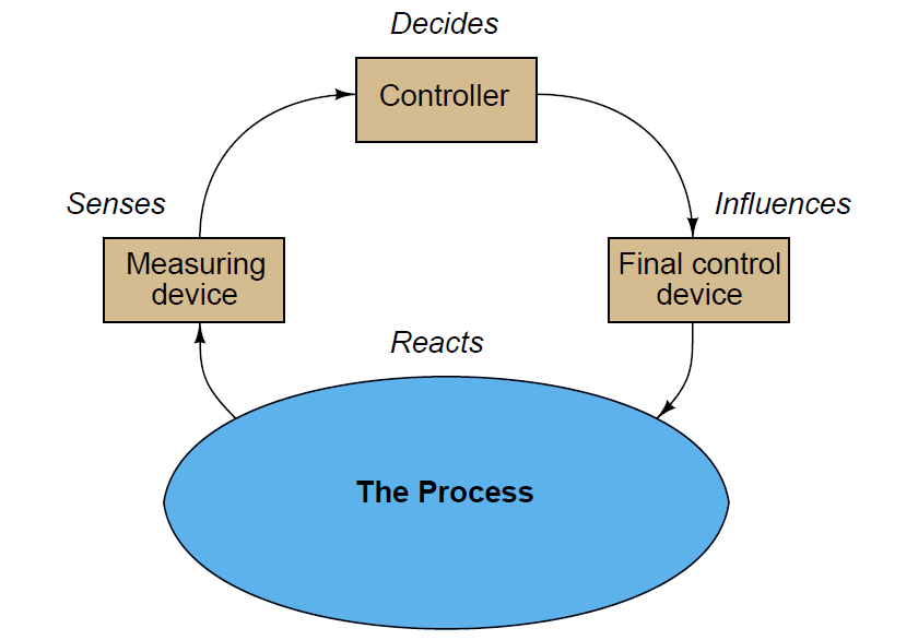
The common home thermostat is an example of a measurement and control system, with the home’s internal air temperature being the “process” under control. In this example, the thermostat usually serves two functions: sensing and control, while the home’s heater adds heat to the home to increase temperature, and/or the home’s air conditioner extracts heat from the home to decrease temperature. The job of this control system is to maintain air temperature at some comfortable level, with the heater or air conditioner taking action to correct temperature if it strays too far from the desired value (called the setpoint).
Industrial measurement and control systems have their own unique terms and standards, which is the primary focus of this article. Here are some common instrumentation terms and their definitions:
Process: The physical system we are attempting to control or measure. Examples: water filtration system, molten metal casting system, steam boiler, oil refinery unit, power generation unit.
Process Variable, or PV: The specific quantity we are measuring in a process. Examples: pressure, level, temperature, flow, electrical conductivity, pH, position, speed, vibration.
Setpoint, or SP: The value at which we desire the process variable to be maintained at. In other words, the “target” value for the process variable.
Primary Sensing Element, or PSE: A device directly sensing the process variable and translating that sensed quantity into an analog representation (electrical voltage, current, resistance; mechanical force, motion, etc.). Examples: thermocouple, thermistor, bourdon tube, microphone, potentiometer, electrochemical cell, accelerometer.
Transducer: A device converting one standardized signal into another standardized instrumentation signal, and/or performing some sort of processing on that signal. Often referred to as a converter and sometimes as a “relay.” Examples: I/P converter (converts 4- 20 mA electric signal into 3-15 PSI pneumatic signal), P/I converter (converts 3-15 PSI pneumatic signal into 4-20 mA electric signal).
Note: in general science parlance, a “transducer” is any device converting one form of energy into another, such as a microphone or a thermocouple. In industrial instrumentation, however, we generally use “primary sensing element” to describe this concept and reserve the word “transducer” to specifically refer to a conversion device for standardized instrumentation signals.
Transmitter: A device translating the signal produced by a primary sensing element (PSE) into a standardized instrumentation signal such as 3-15 PSI air pressure, 4-20 mA DC electric current, Fieldbus digital signal packet, etc., which may then be conveyed to an indicating device, a controlling device, or both.
Lower- and Upper-range values, abbreviated LRV and URV, respectively: the values of process measurement deemed to be 0% and 100% of a transmitter’s calibrated range. For example, if a temperature transmitter is calibrated to measure a range of temperature starting at 300 degrees Celsius and ending at 500 degrees Celsius, its LRV would be 300 oC and its URV would be 500 oC.
Zero and Span: alternative descriptions to LRV and URV for the 0% and 100% points of an instrument’s calibrated range. “Zero” refers to the beginning-point of an instrument’s range (equivalent to LRV), while “span” refers to the width of its range (URV − LRV). For example, if a temperature transmitter is calibrated to measure a range of temperature starting at 300 degrees Celsius and ending at 500 degrees Celsius, its zero would be 300 deg C and its span would be 200 deg C.
Controller: A device receiving a process variable (PV) signal from a primary sensing element (PSE) or transmitter, comparing that signal to the desired value (called the setpoint) for that process variable, and calculating an appropriate output signal value to be sent to a final control element (FCE) such as an electric motor or control valve.
The Controller may be Physical device or a Soft logic created in PLC/DCS systems. Majorly we use PLC/DCS systems soft logic controllers where real input and output devices are connected to this soft controllers.
Final Control Element, or FCE: A device receiving the signal output by a controller to directly influence the process. Examples: variable-speed electric motor, control valve, electric heater.
Manipulated Variable, or MV: The quantity in a process we adjust or otherwise manipulate in order to influence the process variable (PV). Also used to describe the output signal generated by a controller; i.e. the signal commanding (“manipulating”) the final control element to influence the process.
Automatic mode: When the controller generates an output signal based on the relationship of process variable (PV) to the setpoint (SP).
Manual mode: When the controller’s decision-making ability is bypassed to let a human operator directly determine the output signal sent to the final control element.
Now we will explore some practical examples of measurement and control systems so you can get a better idea of these fundamental concepts in next article.