Usually, it is not necessary that only a single current line or voltage line flow through a circuit. Generally, multiple signals related to voltage can flow in a single circuit. You can take a simple example of a three-phase power supply in that case, where three live signals flow in a single circuit.
Related to this theory, there exists a common term for their performance – differential mode and common mode. In this post, we will learn the difference between differential mode and common mode.
What is a Common Mode Signal?
Refer to the below image for understanding. Suppose there are two simple voltage lines, each carrying 2V. These two voltages are out of phase with each other. When one signal is aligned at 90 degrees, the other signal is at 180 degrees. So, they are not in phase with each other.
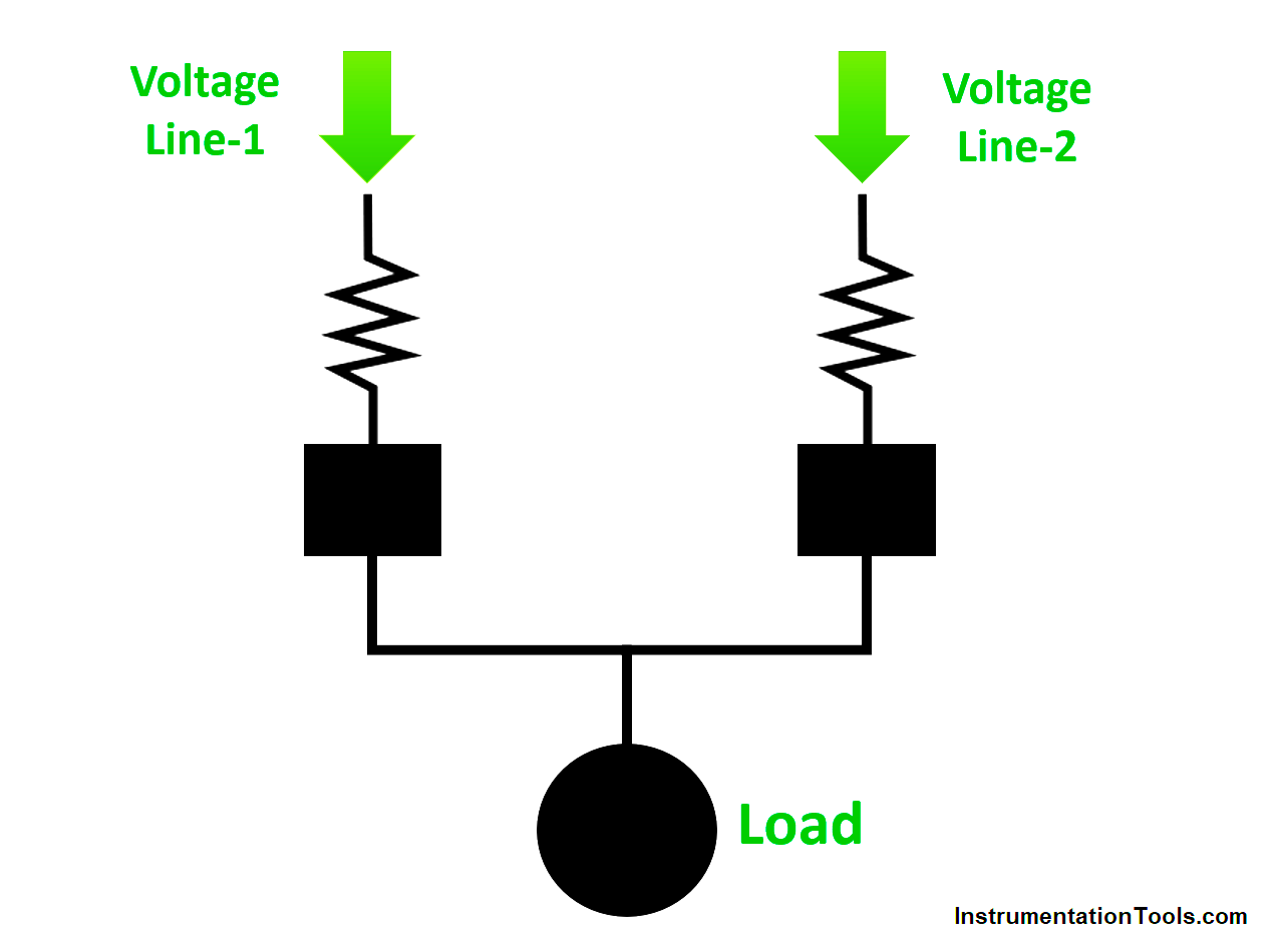
Typically, if we calculate how much is the average voltage flowing through the circuit, it is 2V. It is determined by the formula – VCM = (V1+V2) / 2. Based on the voltage that we have given of 2V, the VCM will thus be at 2V. This type of signaling is called a common mode signal. When the signal flows in the same direction, the common mode voltage is thus calculated.
Now, you must be thinking about how the common mode signal gets its return current path. Well, this is done by a ground path between both of them, joined by a capacitor. This brings impedance in the circuit and allows for the flow of the return current path.
What is a Differential Mode Signal?
Refer to the above image for understanding. Suppose there are two simple voltage lines, each carrying 2V. It is the same as in the common mode signal, but see the major difference here. It can be related to a single-phase voltage line.
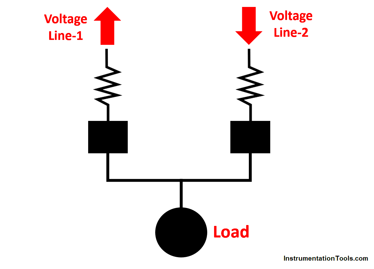
One line will carry the load current, whereas the other line will carry the return current. So, in this case, instead of adding the two voltages, they are subtracted here in this case. This gives a difference between the two lines.
There is no need for a capacitance path here, as the second line itself carries the return current and this gives a differential voltage of the circuit.
Difference Between Differential Mode and Common Mode
Given the concept discussed, it can be easily understood that there is only one major difference between them; the direction of signal flow.
Common mode signal adds the voltage in them due to the same flow direction, whereas differential mode signal subtracts the voltage in them due to the opposite flow direction.
Common Mode Noise and Differential Mode Noise
Now, if we understand further, these concept looks good only in theory. Noise generated in an electronic circuit is mainly classified into these two types
- Common mode noise
- Differential mode noise.
The voltage difference can be caused due to harmonics of nearby surroundings, in the load, or through the ground. In that case, if the normal current was flowing in a common mode way, then it is the common mode noise and if it was flowing in a differential way, then it is the differential mode noise.
It is to be noted that this noise can also be present in DC voltages. Though one part of the DC voltage is always zero, the common addition or the difference too creates an attenuation in it, causing noise to be generated.
Let us clarify it further. Common mode signal will flow in the same direction; so the noise-induced too will flow in the same direction and channeled in both the signal wires. The interference will thus be common in both of them. But, in a differential mode signal, the interference will be the difference between both of them.
In this way, we saw the difference between the differential mode signal and the common mode signal.