To read and understand engineering fluid diagrams and prints, usually referred to as P&IDs, an individual must be familiar with the basic symbols.
Valve Symbols
Valves are used to control the direction, flow rate, and pressure of fluids. Figure 1 shows the symbols that depict the major valve types.
It should be noted that globe and gate valves will often be depicted by the same valve symbol. In such cases, information concerning the valve type may be conveyed by the component identification number or by the notes and legend section of the drawing; however, in many instances even that may not hold true.

Figure 1 : Valve Symbols
Valve Actuators
Some valves are provided with actuators to allow remote operation, to increase mechanical advantage, or both.
Figure 2 shows the symbols for the common valve actuators. Note that although each is shown attached to a gate valve, an actuator can be attached to any type of valve body. If no actuator is shown on a valve symbol, it may be assumed the valve is equipped only with a hand-wheel for manual operation.

Figure 2 : Valve Actuator Symbols
The combination of a valve and an actuator is commonly called a control valve. Control valves are symbolized by combining the appropriate valve symbol and actuator symbol, as illustrated in Figure 2. Control valves can be configured in many different ways. The most commonly found configurations are to manually control the actuator from a remote operating station, to automatically control the actuator from an instrument, or both.
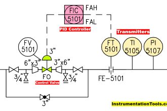
In many cases, remote control of a valve is accomplished by using an intermediate, small control valve to operate the actuator of the process control valve. The intermediate control valve is placed in the line supplying motive force to the process control valve, as shown in Figure 3. In this example, air to the process air-operated control valve is controlled by the solenoid-operated, 3-way valve in the air supply line. The 3-way valve may supply air to the control valve’s diaphragm or vent the diaphragm to the atmosphere.

Figure 3 : Remotely Controlled Valve
Note that the symbols alone in Figure 3 do not provide the reader with enough information to determine whether applying air pressure to the diaphragm opens or closes the process control valve, or whether energizing the solenoid pressurizes or vents the diaphragm. Further, Figure 3 is incomplete in that it does not show the electrical portion of the valve control system nor does it identify the source of the motive force (compressed air). Although Figure 3 informs the reader of the types of mechanical components in the control system and how they interconnect, it does not provide enough information to determine how those components react to a control signal.
Control valves operated by an instrument signal are symbolized in the same manner as those shown previously, except the output of the controlling instrument goes to the valve actuator. Figure 4 shows a level instrument (designated “LC”) that controls the level in the tank by positioning an air-operated diaphragm control valve. Again, note that Figure 4 does not contain enough information to enable the reader to determine how the control valve responds to a change in level.
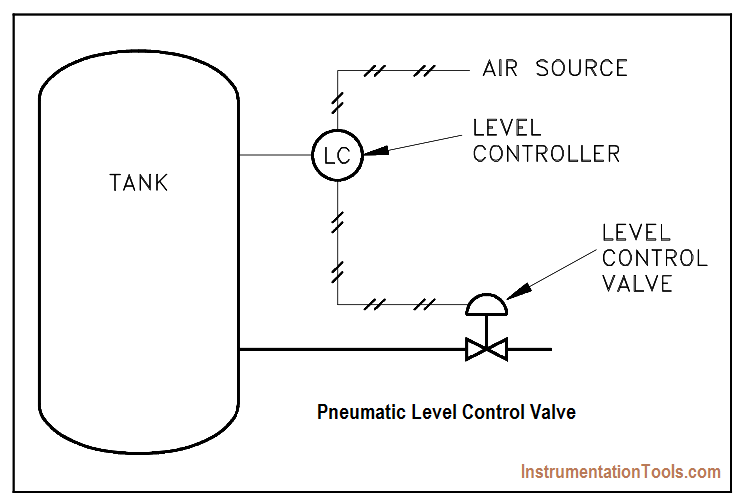
Figure 4 : Level Control Valve
An additional aspect of some control valves is a valve positioner, which allows more precise control of the valve. This is especially useful when instrument signals are used to control the valve. An example of a valve positioner is a set of limit switches operated by the motion of the valve. A positioner is symbolized by a square box on the stem of the control valve actuator. The positioner may have lines attached for motive force, instrument signals, or both.
Figure 5 shows two examples of valves equipped with positioners. Note that, although these examples are more detailed than those of Figure 3 and Figure 4, the reader still does not have sufficient information to fully determine response of the control valve to a change in control signal.

Figure 5 : Control Valves with Valve Positioners
In Example A of Figure 5, the reader can reasonably assume that opening of the control valve is in some way proportional to the level it controls and that the solenoid valve provides an override of the automatic control signals. However, the reader cannot ascertain whether it opens or closes the control valve. Also, the reader cannot determine in which direction the valve moves in response to a change in the control parameter. In Example B of Figure 5, the reader can make the same general assumptions as in Example A, except the control signal is unknown.
Without additional information, the reader can only assume the air supply provides both the control signal and motive force for positioning the control valve. Even when valves are equipped with positioners, the positioner symbol may appear only on detailed system diagrams. Larger, overall system diagrams usually do not show this much detail and may only show the examples of Figure 5 as air-operated valves with no special features.
Control Valve Designations
A control valve may serve any number of functions within a fluid system. To differentiate between valve uses, a balloon labeling system is used to identify the function of a control valve, as shown in Figure 6.
The common convention is that the first letter used in the valve designator indicates the parameter to be controlled by the valve.
For example:
- F = flow
- T = temperature
- L = level
- P = pressure
- H = hand (manually operated valve)
The second letter is usually a “C” and identifies the valve as a controller, or active component, as opposed to a hand-operated valve. The third letter is a “V” to indicate that the piece of equipment is a valve.
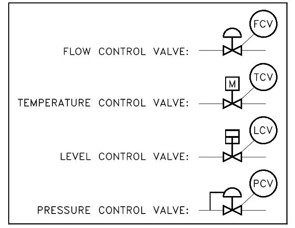
Figure 6 Control Valve Designations
Piping Systems
The piping of a single system may contain more than a single medium. For example, although the main process flow line may carry water, the associated auxiliary piping may carry compressed air, inert gas, or hydraulic fluid. Also, a fluid system diagram may also depict instrument signals and electrical wires as well as piping.
Figure 7 shows commonly used symbols for indicating the medium carried by the piping and for differentiating between piping, instrumentation signals, and electrical wires. Note that, although the auxiliary piping symbols identify their mediums, the symbol for the process flow line does not identify its medium.
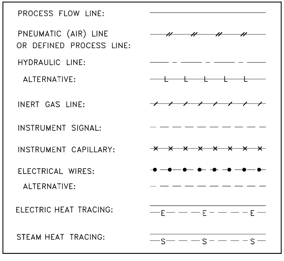
Figure 7 : Piping Symbols
The diagram may also depict the individual fittings comprising the piping runs depending on its intended use.
Figure 8 shows symbols used to depict pipe fittings.
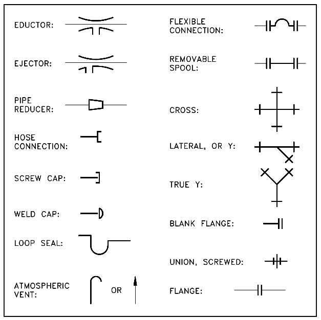
Figure 8 : Piping Symbols
Instrumentation
One of the main purposes of a P&ID is to provide functional information about how instrumentation in a system or piece of equipment interfaces with the system or piece of equipment. Because of this, a large amount of the symbology appearing on P&IDs depicts instrumentation and instrument loops.
The symbols used to represent instruments and their loops can be divided into four categories. Generally each of these four categories uses the component identifying (labeling) scheme identified in Table 1. The first column of Table 1 lists the letters used to identify the parameter being sensed or monitored by the loop or instrument.
The second column lists the letters used to indicate the type of indicator or controller. The third column lists the letters used to indicate the type of component. The fourth column lists the letters used to indicate the type of signals that are being modified by a modifier.
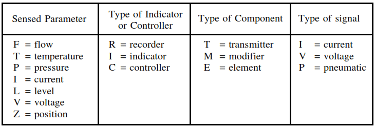
The first three columns above are combined such that the resulting instrument identifier indicates its sensed parameter, the function of the instrument, and the type of instrument. The fourth column is used only in the case of an instrument modifier and is used to indicate the types of signals being modified.
The following is a list of example instrument identifiers constructed from above Table.
- FIC = flow indicating controller
- FM = flow modifier
- PM = pressure modifier
- TE = temperature element
- TR = temperature recorder
- LIC = level indicating controller
- TT = temperature transmitter
- PT = pressure transmitter
- FE = flow element
- FI = flow indicator
- TI = temperature indicator
- FC = flow controller
Sensing Devices and Detectors
The parameters of any system are monitored for indication, control, or both. To create a usable signal, a device must be inserted into the system to detect the desired parameter. In some cases, a device is used to create special conditions so that another device can supply the necessary measurement.
Figure 9 shows the symbols used for the various sensors and detectors.

Figure 9 : Sensing Device Symbols
Modifiers and Transmitters
Sensors and detectors by themselves are not sufficient to create usable system indications. Each sensor or detector must be coupled with appropriate modifiers and/or transmitters. The exceptions are certain types of local instrumentation having mechanical readouts, such as bourdon tube pressure gauges and bimetallic thermometers. Figure 10 illustrates various examples of modifiers and transmitters. Figure 10 also illustrates the common notations used to indicate the location of an instrument, i.e., local or board mounted.
Transmitters are used to convert the signal from a sensor or detector to a form that can be sent to a remote point for processing, controlling, or monitoring. The output can be electronic (voltage or current), pneumatic, or hydraulic. Figure 10 illustrates symbols for several specific types of transmitters.
The reader should note that modifiers may only be identified by the type of input and output signal (such as I/P for one that converts an electrical input to a pneumatic output) rather than by the monitored parameter (such as PM for pressure modifier).
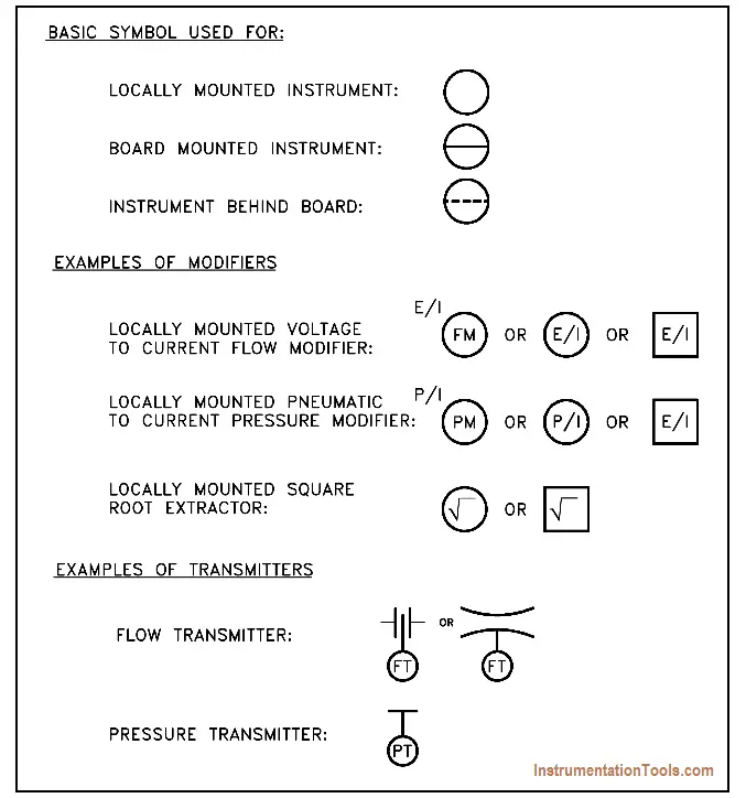
Figure 10 : Transmitters and Instruments
Indicators and Recorders
Indicators and recorders are instruments that convert the signal generated by an instrument loop into a readable form. The indicator or recorder may be locally or board mounted, and like modifiers and transmitters this information is indicated by the type of symbol used.
Figure 11 provides examples of the symbols used for indicators and recorders and how their location is denoted.
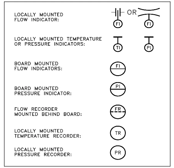
Figure 11 : Indicators and Recorders
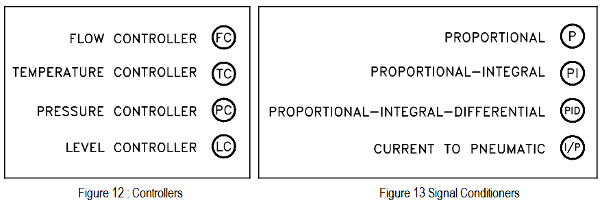
Controllers
Controllers process the signal from an instrument loop and use it to position or manipulate some other system component. Generally they are denoted by placing a “C” in the balloon after the controlling parameter as shown in Figure 12. There are controllers that serve to process a signal and create a new signal.
These include proportional controllers, proportional-integral controllers, and proportional-integral-differential controllers. The symbols for these controllers are illustrated in Figure 13. Note that these types of controllers are also called signal conditioners.
Examples of Simple Instrument Loops
Figure 14 shows two examples of simple instrument loops. Figure 14 (A) shows a temperature transmitter (TT), which generates two electrical signals. One signal goes to a board mounted temperature recorder (TR) for display. The second signal is sent to a proportional-integral-derivative (PID) controller, the output of which is sent to a current-to-pneumatic modifier (I/P). In the I/P modifier, the electric signal is converted into a pneumatic signal, commonly 3 psi to 15 psi, which in turn operates the valve.
The function of the complete loop is to modify flow based on process fluid temperature. Note that there is not enough information to determine how flow and temperature are related and what the setpoint is, but in some instances the setpoint is stated on a P&ID. Knowing the setpoint and purpose of the system will usually be sufficient to allow the operation of the instrument loop to be determined.
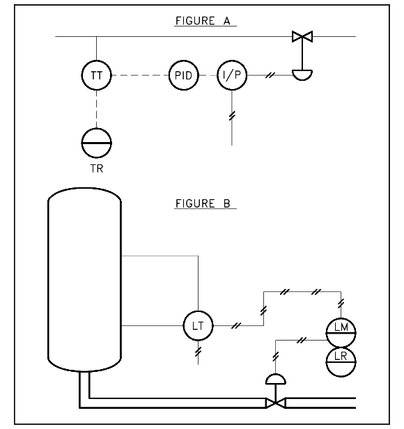
Figure 14 : Instrumentation System Examples
The pneumatic level transmitter (LT) illustrated in Figure 14 (B) senses tank level. The output of the level transmitter is pneumatic and is routed to a board-mounted level modifier (LM). The level modifier conditions the signal (possibly boosts or mathematically modifies the signal) and uses the modified signal for two purposes.
The modifier drives a board-mounted recorder (LR) for indication, and it sends a modified pneumatic signal to the diaphragm-operated level control valve. Notice that insufficient information exists to determine the relationship between sensed tank level and valve operation.
Components
Within every fluid system there are major components such as pumps, tanks, heat exchangers, and fans. Figure 15 shows the engineering symbols for the most common major components.
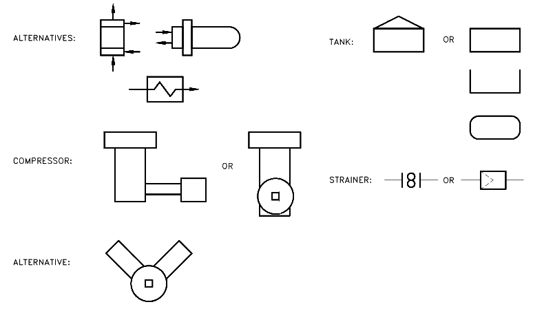
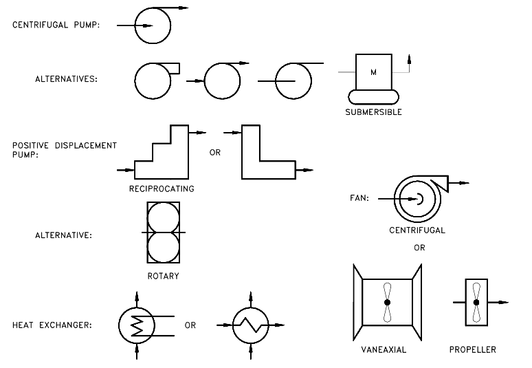
Figure 15 : Symbols for Major Components
Miscellaneous P&ID Symbols
In addition to the normal symbols used on P&IDs to represent specific pieces of equipment, there are miscellaneous symbols that are used to guide or provide additional information about the drawing.
Figure 16 lists and explains four of the more common miscellaneous symbols.

Figure 16 : Miscellaneous Symbols


Very clearifying -Thanks for sharing!!!