Inst ToolsInst ToolsInst Tools
  • Courses
  • Automation
    • PLC
    • Control System
    • Safety System
    • Communication
    • Fire & Gas System
  • Instrumentation
    • Design
    • Pressure
    • Temperature
    • Flow
    • Level
    • Vibration
    • Analyzer
    • Control Valve
    • Switch
    • Calibration
    • Erection & Commissioning
  • Interview
    • Instrumentation
    • Electrical
    • Electronics
    • Practical
  • Q&A
    • Instrumentation
    • Control System
    • Electrical
    • Electronics
    • Analog Electronics
    • Digital Electronics
    • Power Electronics
    • Microprocessor
  • Request
Search
  • Books
  • Software
  • Projects
  • Process
  • Tools
  • Basics
  • Formula
  • Power Plant
  • Root Cause Analysis
  • Electrical Basics
  • Animation
  • Standards
  • 4-20 mA Course
  • Siemens PLC Course
Reading: Design Counters in PLC Programming With a Move Instruction
Share
Font ResizerAa
Inst ToolsInst Tools
Font ResizerAa
  • Courses
  • Design
  • PLC
  • Interview
  • Control System
Search
  • Courses
  • Automation
    • PLC
    • Control System
    • Safety System
    • Communication
    • Fire & Gas System
  • Instrumentation
    • Design
    • Pressure
    • Temperature
    • Flow
    • Level
    • Vibration
    • Analyzer
    • Control Valve
    • Switch
    • Calibration
    • Erection & Commissioning
  • Interview
    • Instrumentation
    • Electrical
    • Electronics
    • Practical
  • Q&A
    • Instrumentation
    • Control System
    • Electrical
    • Electronics
    • Analog Electronics
    • Digital Electronics
    • Power Electronics
    • Microprocessor
  • Request
Follow US
All rights reserved. Reproduction in whole or in part without written permission is prohibited.
Inst Tools > Blog > PLC Tutorials > Design Counters in PLC Programming With a Move Instruction

Design Counters in PLC Programming With a Move Instruction

In this article, we will learn how to design counters in PLC programming with a move and add instruction.

Last updated: August 8, 2023 3:01 pm
Viral Nagda
PLC Tutorials
1 Comment
Share
5 Min Read
SHARE

Counters are a very important instruction in PLC programming. You require it in almost every logic. Be it counting something to counting events, counters form an important part of PLC programming.

Contents
CountersDesign Counters in PLC With a Move Instruction

Because event count is used in many applications and it helps PLC programmers save time in writing cumbersome coding. But, many times, it is always required to find a backup solution for a plan if it does not work.

In the case of counters too, a PLC programmer must know a backup logic if it does not work properly. For that, two instructions can be combined and written – move and addition.

In this post, we will learn how to design counters in PLC programming with a move and add instruction.

Counters

First of all, we will see a counter instruction on how it is written. Refer to the below image. As you can see, a counter has three inputs – count, reset, and set value; and has two outputs – done and current value.

A count input is required to provide the counter with a pulse for counting it, a reset input is required to reset the counter, and a set value is required for feeding the counter with set counts. A done output is used to denote that the counter has finished counting and the current value shows the present value of counts that the counter has counted till now.
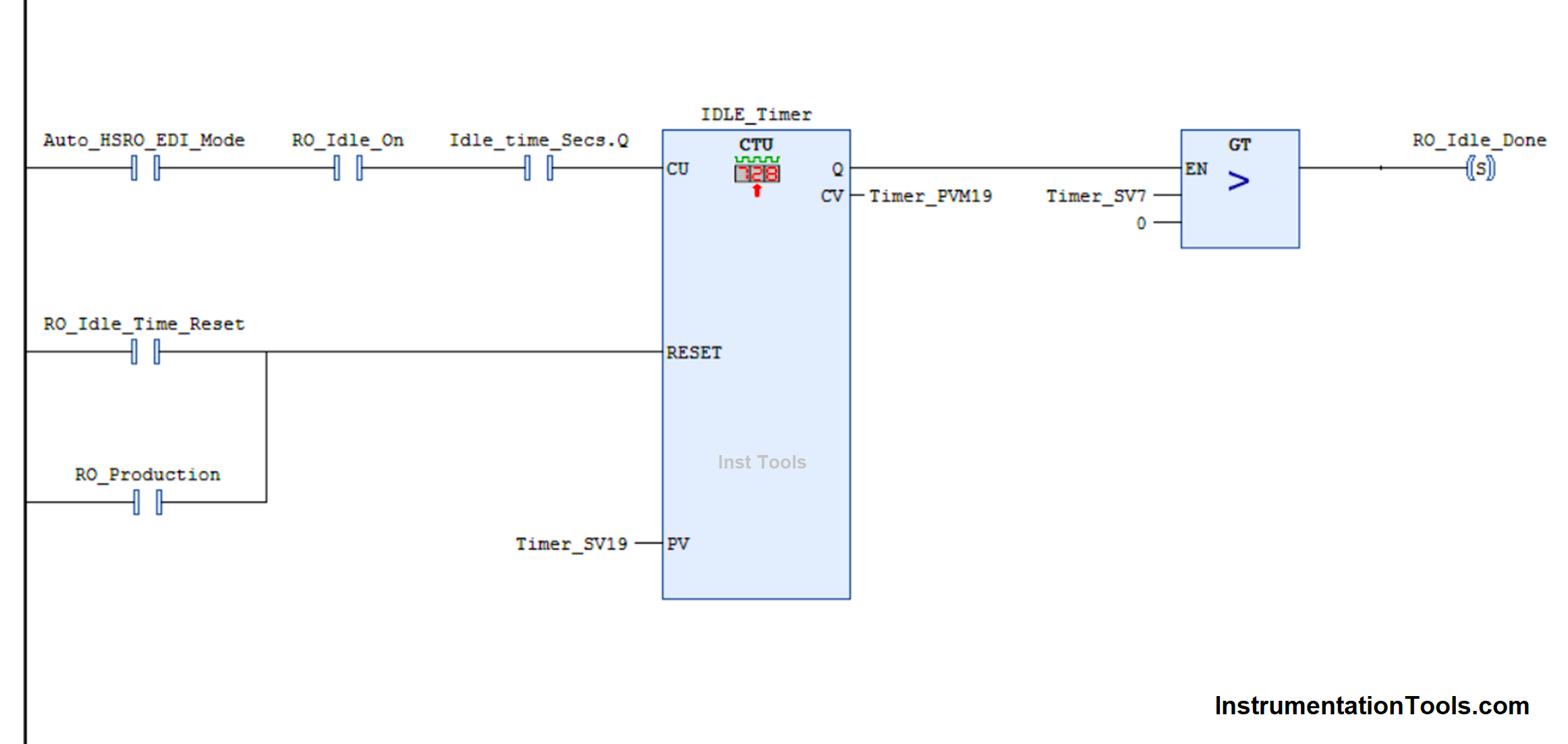
How to Use Counters in PLC

When count input is received, the counter increments by a value. The count input works on a pulse basis and not on a continuous basis. When the counter reaches its set count, then the output done bit goes on.

The only way to then turn it off is by giving the reset input. The count value will become zero on this input and the counter resets due to this. It is to be noted that even if the count has been reached and you still give count input, then too the count will go on incrementing.

You can also see that a comparison block is used after counter output, which allows it to pass to the final bit to be turned on. This prevents the final bit from turning on unnecessarily if the set count is zero.

Design Counters in PLC With a Move Instruction

Now, we will see how to write this same coding with the help of move and add instructions. Refer to the below image. In the first rung, the count input is replaced with an add instruction.

The addition will happen if the input condition is true, and that too with a pulse. Pulse must be used, otherwise, continuous addition will go on and there will be no control over it.
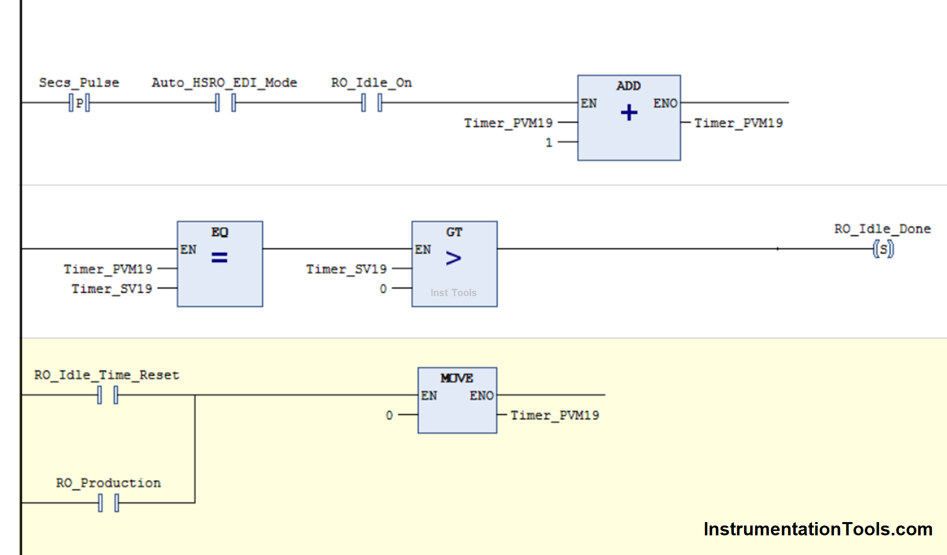
Design Counters in PLC Programming With a Move Instruction

In the second rung, it compares whether the set counts have been reached or not. It also checks whether the set count is more than zero or not. If these conditions are true, then the output turns on.

In the third rung, the counter value becomes zero on the receipt of the corresponding inputs. This equals the operation of reset input.

These three rungs are enough to replicate the function of a counter. You can use either a counter or this PLC logic, according to your needs. But, it is to be noted that we can program a counter by writing this way too.

In this way, we saw how to write counters in PLC programming with a move and add instruction.

If you liked this article, then please subscribe to our YouTube Channel for Instrumentation, Electrical, PLC, and SCADA video tutorials.

You can also follow us on Facebook and Twitter to receive daily updates.

Read Next:

  • Omron PLC Online Training Course
  • Difference Between PNP and NPN Sensor
  • Light Tower in Industrial Automation
  • Batch Simulator PLC Example Program
  • PLC Program for Stage Control Project
Don't Miss Our Updates
Be the first to get exclusive content straight to your email.
We promise not to spam you. You can unsubscribe at any time.
Invalid email address
You've successfully subscribed !

Continue Reading

PLC Raw Count Calculation for Pressure Transmitter
What is a Surge Protection Device? – Principle, Types, Advantages
STL Programming – SET, RESET, ASSIGN
Ladder Diagram Example using Memory Bits and Set Coils
#7 PLC Best Practices – Validate and Alert for Paired Inputs/Outputs
PLC Automatic Irrigation System
Share This Article
Facebook Whatsapp Whatsapp LinkedIn Copy Link
Share
1 Comment
  • NUNO SILVA says:
    August 9, 2023 at 1:44 pm

    More products information

    Reply

Leave a Reply Cancel reply

Your email address will not be published. Required fields are marked *

Stay Connected

128.3kFollowersLike
69.1kFollowersFollow
210kSubscribersSubscribe
38kFollowersFollow

Categories

Explore More

Different Types of Schneider PLC
Your First Steps Through STL Language
Inside the PLC Control Panel: How Much Do You Know?
Pump and Mixer Operations Example: PLC Timer-Based Control
Automatic Vacuum Cleaner Programming in Omron PLC
Vijeo Designer software – Import and Export
PLC Program for Washing Machine
PLC Program for Positive Edge Pulse Output for One Scan Cycle

Keep Learning

PLC Automation Memory

What is NOR Flash Memory in PLC?

Data Types in PLC

Data Types in PLC – Bit, Byte, Integer, Real, String

Rewire Tool

What is Rewire Tool in Simatic Manager?

TIA Portal MOVE Instruction

MOVE Instruction in PLC – What You Need to Know?

PLC Program for Analog Input Sampling

PLC Analog Input Sampling Ladder Logic

PLC Tag Naming Conventions

PLC Tag Naming Conventions

HMI screen for operator

Auto Tiffin Box Filling Station

DCS

DCS

Learn More

Instrument Control Package (ICP)

Package Control and Safety Systems Implementation Methods

Electrical Machines Questions and Answers

Synchronous Machines Flux and MMF Phasors Questions

Valve Seat leakage Test

Valve Seat Leakage Test

Design Process Control & Safety Systems

Design View of Supplying Process Control and Safety Systems

Ethernet Switch Animation

Ethernet Bus Animation

Why 4-20 mA Current Signal is used instead of Voltage Signal

Why 4-20 mA Current Signal is used instead of Voltage Signal?

Linear Programming in Excel

How to Do Linear Programming in Excel?

DP transmitter installation

Water and Steam Circuits in Power Plants

Menu

  • About
  • Privacy Policy
  • Copyright

Quick Links

  • Learn PLC
  • Helping Hand
  • Part Time Job

YouTube Subscribe

Follow US
All rights reserved. Reproduction in whole or in part without written permission is prohibited.
Welcome Back!

Sign in to your account

Username or Email Address
Password

Lost your password?