A technical innovation in the 1980’s called HART (Highway Addressable Remote Transmitter) gave 4-20 mA loop-powered field instruments the ability to communicate digital as well as analog data.
Today it remains one of the most popular industrial networking standards for field devices.
HART Communicator
HART is an acronym for Highway Addressable Remote Transducer. It is a convenient method of transmitting and receiving digital data along the analog 4-20mA process loop. The HART communication protocol operates using a frequency shift keying method based on the Bell 202 communication standard.
That is, HART uses two frequencies of a sine wave super-imposed on the DC signal cables of the process loop to represent a set and clear bit. A 0 bit is represented by a 1200Hz sine wave, and a 1 bit uses a 2400Hz sine wave. Because the average (DC) value of a sine wave is zero, the 4-20mA DC signal is not affected. The amplitude of the sine wave is approximately equivalent to ±0.5mA.

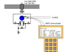
Connect HART Communicator to Transmitter at Calibration Lab

Connect a loop-powered differential pressure transmitter (with HART capability along with analog 4- 20 mA output) to a DC voltage source, a milliammeter, a 250 ohm resistor, HART communicator and a diode as shown in the figure.
Schematic Diagram
The schematic diagram shows the above figure connections in the circuit form.

Connect HART Communicator to Transmitter at Field

HART Communicator Questions
We power-up the transmitter and it is now functioning, answer the following questions:
Question 1:
Use the HART communicator device to access the transmitter’s programmable parameters. Explain which the parameters you are able to access, and explain (if you can) what they mean.
Question 2:
If we use a digital oscilloscope connected in parallel with the transmitter to capture one of the HART data communication bursts. What does this data look like on the oscilloscope display?
Question 3:
Temporarily short past the resistor with a jumper wire and note whether or not this has any affect on the HART data communications.
Question 4:
Why HART communicator needs 250 ohm resistor to connect with a transmitter?
Question 5:
What are the Device Description (DD) files?
Question 6:
What is the use of PV Damping in a HART transmitter?
Question 7:
Explain Sensor Trim and Output Trim?
Question 8:
How do you setup a new transmitter using HART communicator?
Question 9:
What is the use of Square-root function in HART transmitter?
Question 10:
How to do Loop test using HART communicator?
Question 11:
How to configure sensor fail status using HART communicator?
Question 12:
What is the use of fail-safe option & how to configure using HART communicator?
Question 13:
What is the purpose of polling address and burst mode in HART?
Question 14:
How many HART communicators can be connected to a transmitter at a time?
Question 15:
What is the use of Write Protect option in HART communicator?
Question 16:
How to diagnostic a failed smart transmitter?
Share your answers with us through comments.
Credits: Tony R. Kuphaldt
Read Next:
- HART Protocol Questions
- Compare Fielbus & HART
- HART Communication Tutorial
- Wireless HART Protocol
- Configure a Smart Transmitter


similarities and differences between HART 275,375, and 475
Ans plzzz