The conveyor sorting machine is widely used in packing machines in industries that require the function of sorting the number of products and counting the number of products that have been packed.
Conveyor Sorting Machine
This PLC program consists of 2 Sequences, the first sequence serves to calculate the number of Products that will enter the BOX. The second sequence serves to calculate the number of BOXES that have been filled with Product.
Sequence One:
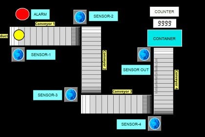
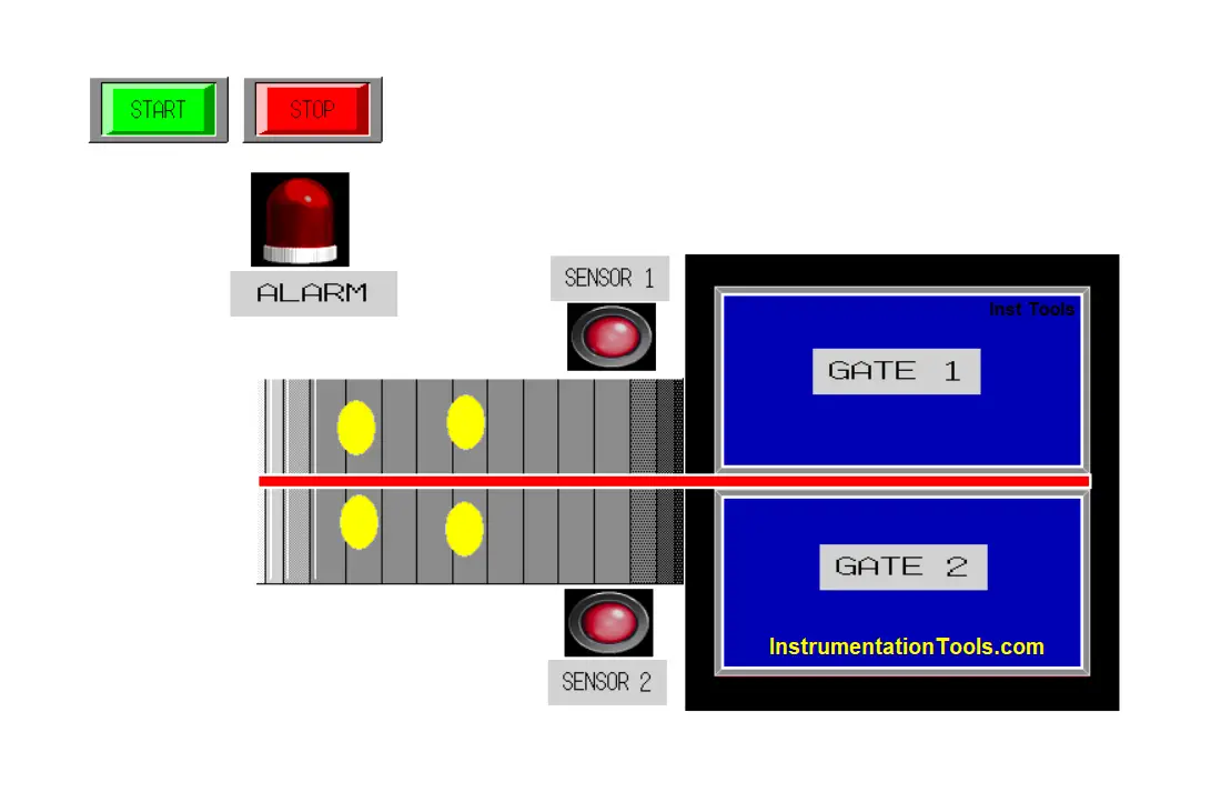
In the first sequence of the system, products sent by Conveyor 1 will be accommodated in GATE1 and GATE 2. Products that will enter GATE 1 and GATE 2 will be detected by SENSOR 1 and SENSOR 2 and then will be counted using the Counter function.
The number of products accommodated by GATE 1 and GATE 2 must be the same. When the Product has reached the desired amount / Set value, GATE 1 and GATE 2 will open, and the product will fall and be accommodated into the BOX below it (as in the second Sequence picture).
In the picture of Sequence 1 can be seen, that the products sent by Conveyor 1 are divided into 2 paths. 1 lane towards the GATE 1 shelter and 1 lane towards GATE 2. Products passing on both paths must run simultaneously or only be delivered 5 seconds late.
If within 5 seconds there is only 1 product detected in one lane then the Alarm will turn ON or if within 2 Minutes there is no product passing in both lanes then the Alarm will turn ON.
Sequence Two:
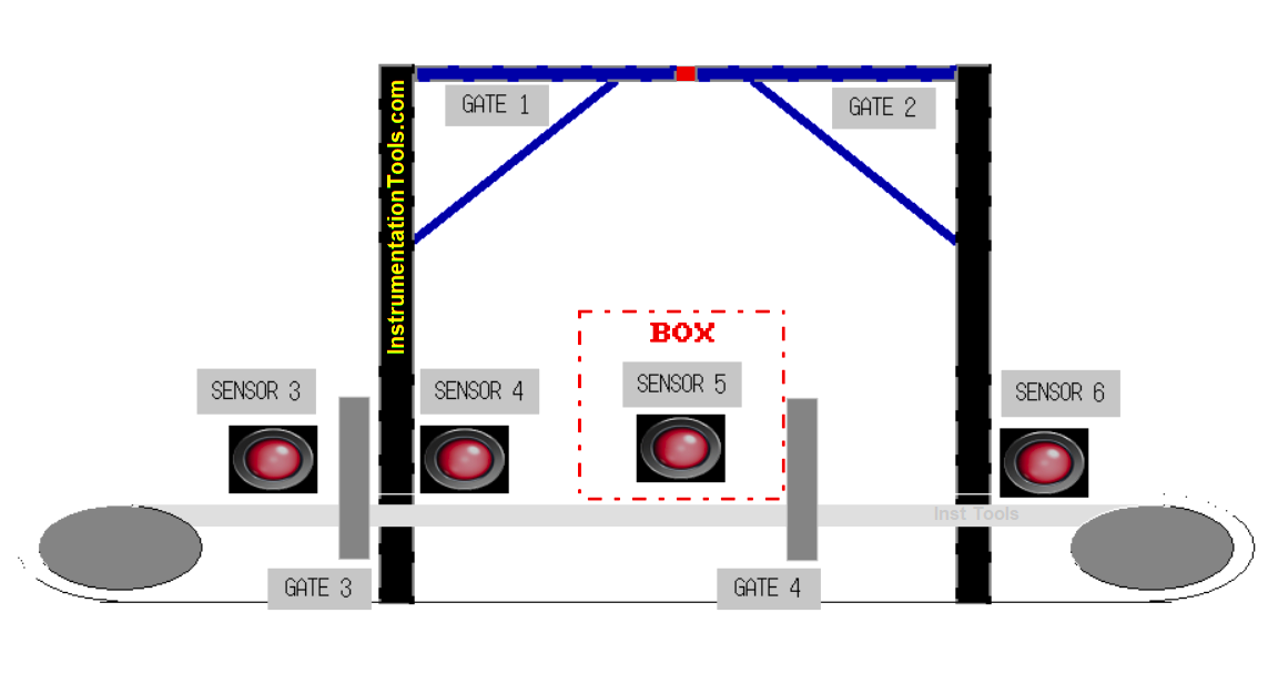
In this sequence, GATE 1 and GATE 2 will only open and drop the product into the BOX, if there is a BOX that stops in the SENSOR 5 area because it is held back by GATE 4 closing.
The normal condition of GATE 3 and 4 is when there is no BOX is open, when there is a BOX entering then GATE 3 will remain open and when the BOX has passed SENSOR 4 then GATE 4 will close to hold the BOX.
GATE 3 will close when SENSOR 3 detects that there is a BOX that will enter and there is still a BOX inside so the new BOX that will enter will be held by GATE 3 until the BOX inside has come out.
SENSOR 6 serves to calculate the number of BOXES that have come out and serves to reset GATE 1 and 2 Counter data.
Conveyor 1 and Conveyor 2 in this system will run continuously and only stop if there is a Motor/Conveyor FAULT or if the STOP button is activated.
Addressing of the System
The list of addresses is shown in the below table.
| Comment | Input (I) | Output (Q) | Bit Memory | Word Memory | TIMERS |
| PB_START | %I0.0 | ||||
| PB_STOP | %I0.1 | ||||
| SENSOR_1 | %I0.2 | ||||
| SENSOR_2 | %I0.3 | ||||
| SENSOR_3 | %I0.4 | ||||
| SENSOR_4 | %I0.5 | ||||
| SENSOR_5 | %I0.6 | ||||
| SENSOR_6 | %I0.7 | ||||
| FB_GATE_1 | %I0.8 | ||||
| FB_GATE_2 | %I0.9 | ||||
| FB_GATE_3 | %I0.12 | ||||
| FB_GATE_4 | %I0.13 | ||||
| CONV_1_FAULT | %I0.10 | ||||
| CONV_2_FAULT | %I0.14 | ||||
| CONV_1_ON | %I0.11 | ||||
| CONV_2_ON | %I0.15 | ||||
| CONV_1 | %Q0.0 | ||||
| CONV_2 | %Q0.7 | ||||
| GATE_1 | %Q0.1 | ||||
| GATE_2 | %Q0.2 | ||||
| GATE_3 | %Q0.4 | ||||
| GATE_4 | %Q0.5 | ||||
| ALARM_1 | %Q0.6 | ||||
| ALARM_2 | %Q0.3 | ||||
| IR_1 | %M0 | ||||
| IR_2 | %M1 | ||||
| IR_TIMER | %M2 | ||||
| IR_CONV_1_ON | %M3 | ||||
| IR_CONV_1_FAULT | %M4 | ||||
| IR_3 | %M5 | ||||
| IR_CONV_2_ON | %M6 | ||||
| IR_CONV_2_FAULT | %M7 | ||||
| COUNT_1 | %MW0 | ||||
| COUNT_2 | %MW1 | ||||
| COUNT_3 | %MW2 | ||||
| TIMER_0 | %TM0 | ||||
| TIMER_1 | %TM1 | ||||
| TIMER_2 | %TM2 |
PLC Sorting Program with Calculation Function
Initial Setup
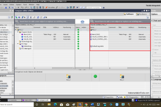
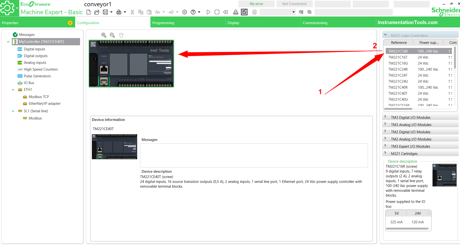
Open Ecostruxure Machine-Basic Software, and enter the Configuration menu to set the type of PLC used, and Digital Input / Output contact settings to be used.
Choose PLC type PLC as needed, in this program, I use type TM221CE40T. To change or add PLC we can click the type of PLC in the list column and then drag it to the work page as shown below.
Set Up Digital Input Contacts
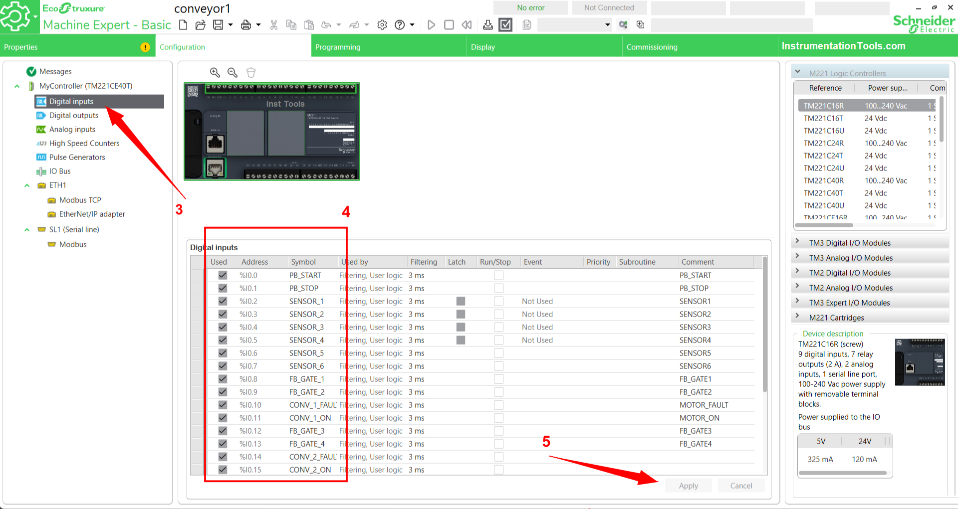
To set the Digital Input contact parameters we have to press the Digital Input sub-menu first, then a list of Digital Input contact address parameters will appear on the work page as shown below. Select the number of contacts to use, then name the SYMBOL column (as shown in box no.4).
The program uses 16 Digital Inputs. When finished, click the “Apply” button to apply the settings that have been done. In Ecostruxure Machine-Basic Software, the Digital Input address uses the format %I0.0 – %I0.xxx.
Set Up Digital Contact Output
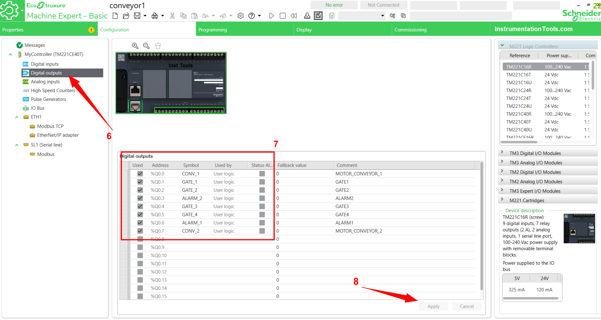
Just like the method in setting Digital Input, we need to click the Digital Output Sub menu then a list of Digital Output parameters will appear on the work page. Give a name/label to the SYMBOL column, in this program using 8 Digital Output contacts. We can also add a description of each address in the comment field.
When finished, click the “Apply” button to apply the settings that have been done. In Ecostruxure Machine-Basic Software the Digital address output address uses the format %Q0.0 – %Q0.xxx.
The next step is to enter the Programming Sub menu to create a Program. Create a Program as follows.
PLC Programming Explanation
The PLC logic is explained below.
NETWORK 0
Rung 0 serves as a latching system. When PB_START (%I0.0) is activated momentarily, Bit memory IR_1 (%M0) will be active, CONV_1 (%Q0.0) and CONV_2 (%Q0.7) will also be active at the same time.
The system will shut down if PB_STOP (%I0.1) is enabled or if the NC (Normally Close) contact of IR_CONV_1_FAULT (%M4) and IR_CONV_2_FAULT (%M7) bit memory is active.
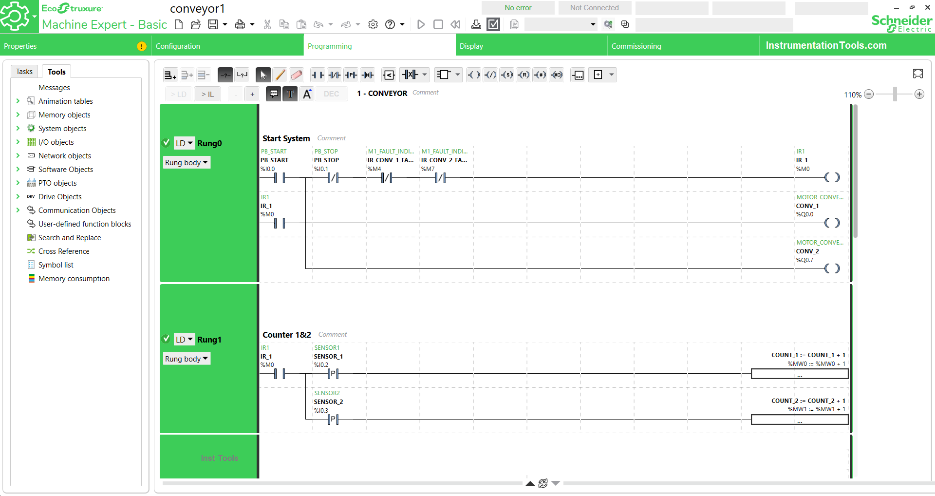
NETWORK 1
This rung serves as a counter for counter data from products detected SENSOR_1 (%I0.2) and SENSOR_2 (%I0.3).
When SENSOR_1 (%I0.2) and SENSOR_2 (%I0.3) detect passing products, the Operation Block records incoming “+1” data in the Word memory allocation COUNT_1 (%MW0) and COUNT_2 (%MW1).
NETWORK 2
Rung 2 manages the process of opening and closing GATE 1 (%Q0.1) and GATE 2 (%Q0.2).
When one of the NO (Normally Open) contacts of SENSOR_1 (%I0.2) or SENSOR_2 (%I0.3) is active it activates bit memory IR_2 (%M1), at the same time it activates Instruction TIMER_0 (%TM0).
The Latching function of bit memory IR_2 (%M1) keeps programs on Rung 2 running even though SENSOR_1 (%I0.2) or SENSOR_2 (%I0.3) inactive.
When TIMER_0 (%TM0) has reached its Preset value then IR_TIMER (%M2) will be active and will turn off bit memory IR_2 (%M1) using the Interlock function.
The Latching function will be replaced by IR_2 (%M1) bit memory. When the data values of Word memory COUNT_1 (%MW0) and COUNT_2 (%MW1) are the same and the NO (Normally Open) contact of SENSOR_5 (%I0.6) is active, TIMER_1 (%TM1) which is of type Timer Of Delay will activate GATE_1 (%Q0.1) and GATE_2 (%Q0.2) for 2 seconds.
When GATE_1 (%Q0.1) and GATE_2 (%Q0.2) are active, the NC (Normally Close) contacts of bit memory FB_GATE_1 (%I0.8) and FB_GATE_2 (%I0.9) turn ON and TIMER_0 (%TM0) stops.
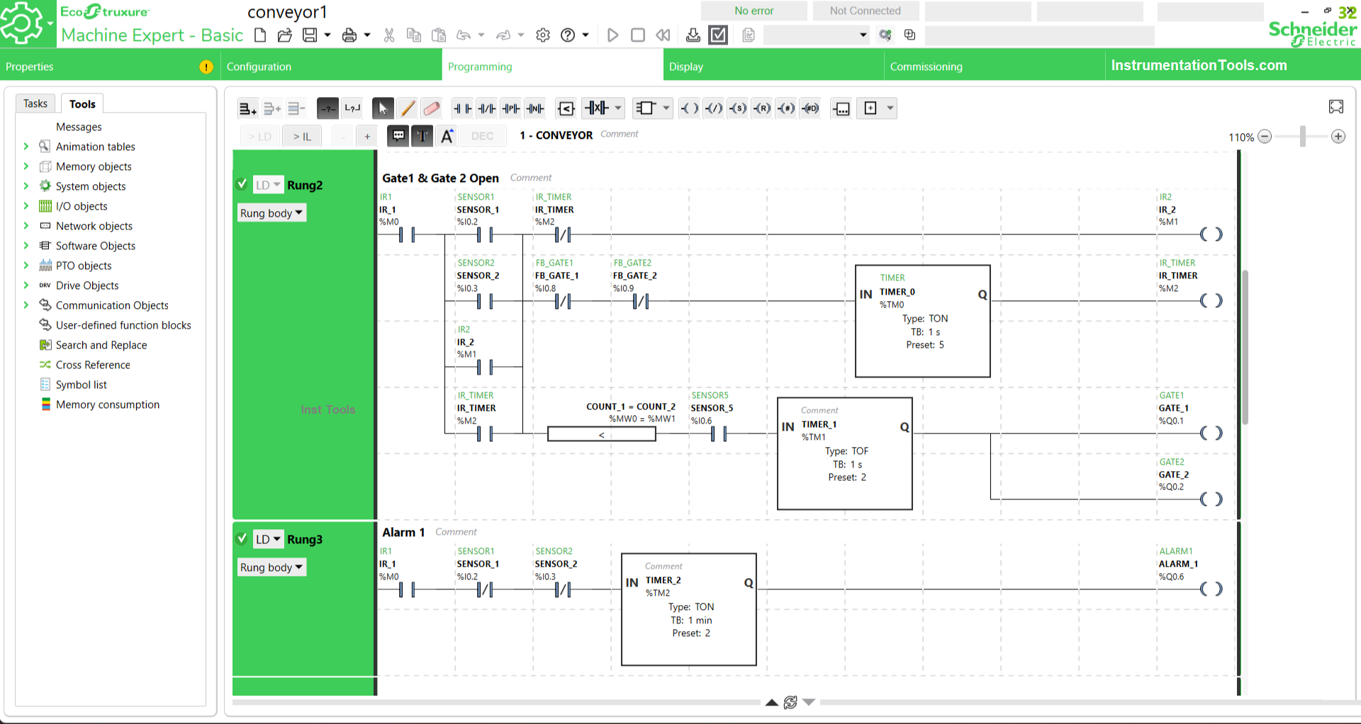
NETWORK 3
This rung functions as an ALARM if within 2 minutes no Product is detected on Conveyor 1.
When IR_1 (%M0) is active it will activate TIMER_2 (%TM2) if before 2 minutes there is a detected Product then the NC (Normally Close) contact of SENSOR_1 (%I0.2) or SENSOR_2 (%I0.3) will activate and turn off TIMER_2 (%TM2).
Because TIMER_2 (%TM2) is not a Retentive timer type, it cannot store the last value.
NETWORK 4
Rung 4 activates ALARM_2 (%Q0.3) if the data in Word memory COUNT_1 (%MW0) and COUNT_2 (%MW1) are not the same.
NETWORK 5
Rung 5 functions to regulate the OPEN and CLOSE system of GATE_3 (%Q0.4). When 1 box is entered, SENSOR_5 (%I0.6) will be ACTIVE continuously, but GATE_3 (%Q0.4) is still OPEN.
When another BOX is detected by SENSOR_3 (%0.4) then GATE_3 (%Q0.4) will CLOSE. When SENSOR_5 (%I0.6) is deactivated and SENSOR_6 (%I0.7) detects that the BOX has come out, GATE_3 (%Q0.4) will OPEN and the BOX that was previously stuck will ENTER.
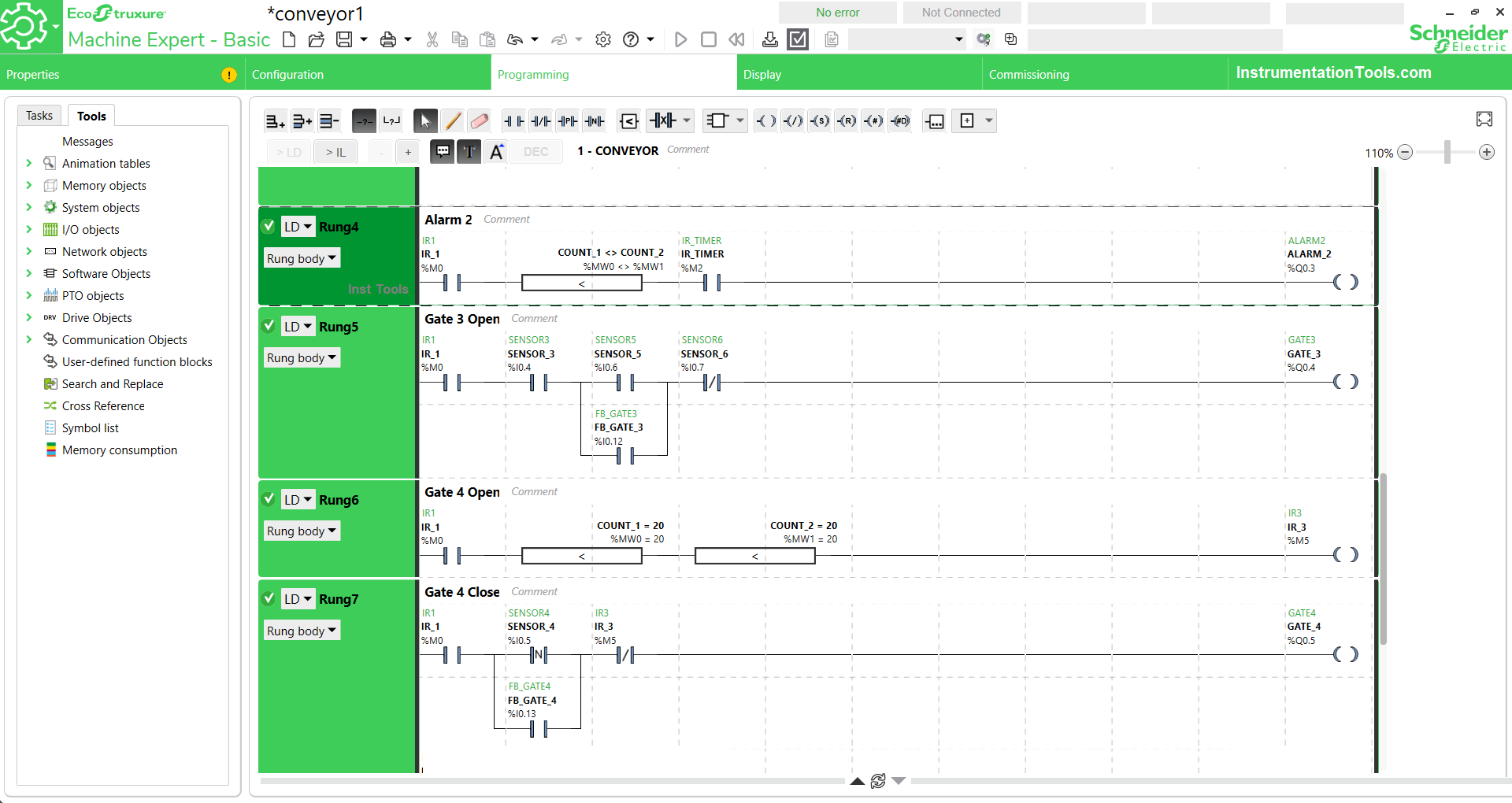
NETWORK 6
This rung serves to open GATE_4 (%Q0.5) using the Interlock Function of IR_3 (%M5) bit memory.
When Word memory data COUNT_1 (%MW0) and COUNT_2 (%MW1) are the same, it activates bit memory IR_3 (%M5) which has an Interlock Function in Rung 7, resulting in GATE_4 (%Q0.5) opening.
NETWORK 7
When SENSOR_4 (%I0.5) is active for a moment, that is, when the BOX has passed SENSOR_4 (%I0.5), the GATE_4 (%Q0.5) will close to hold the BOX.
FB_GATE_4 (%I0.13) functions as Latching on this Rung and when the NC (Normally Close) contact of IR_3 (%M5) is active then GATE_4 (%Q0.5) will open.
NETWORK 8
This rung serves to record data COUNT_3 (%MW2) and reset data from COUNT_1 (%MW0) and COUNT_2 (%MW1) when SENSOR_6 (%I0.7) is active, that is when the BOX has exited.
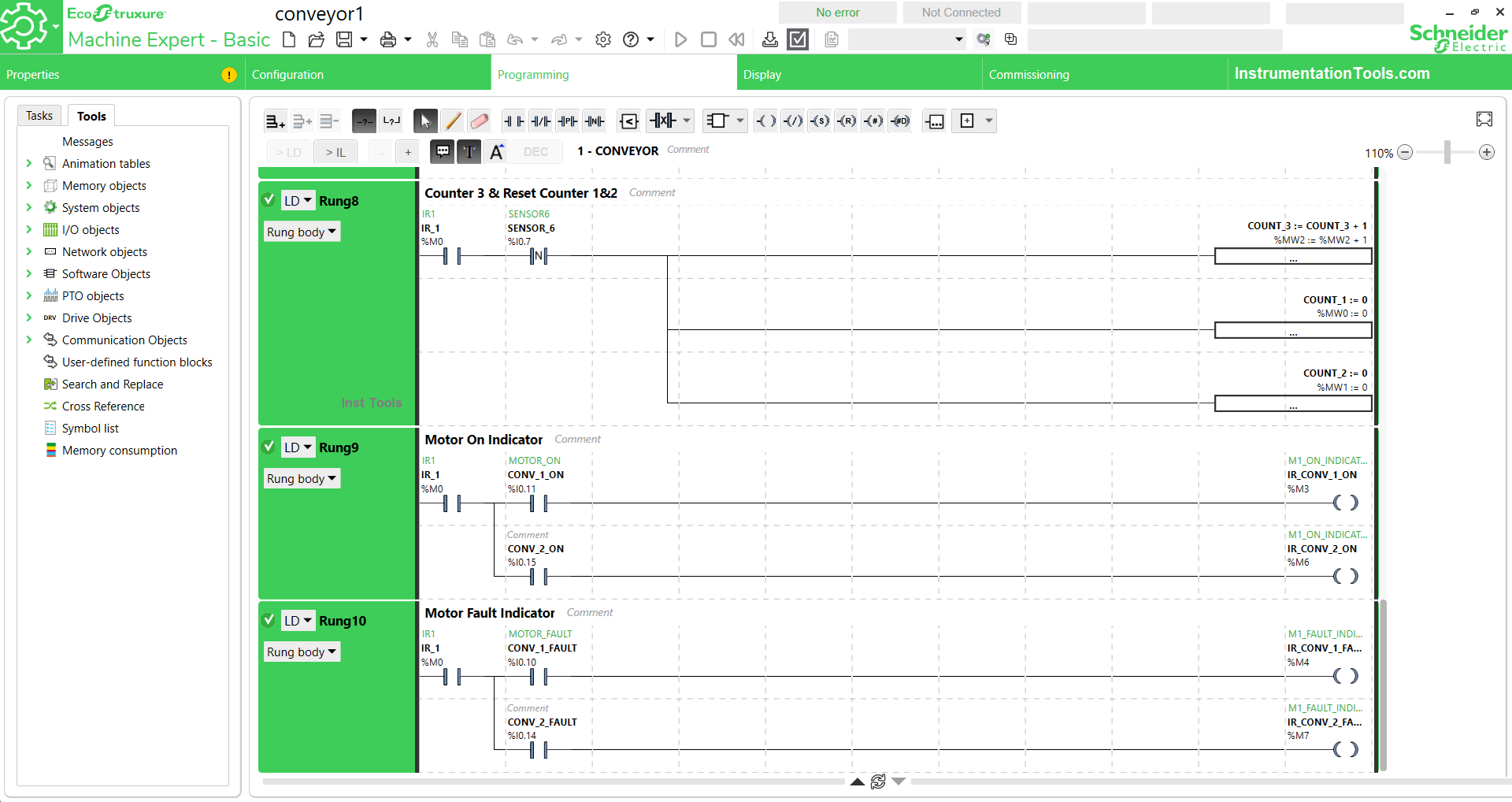
NETWORK 9
This rung activates bit memory IR_CONV_1_ON (%M3) and IR_CONV_2_ON (%M3) for the Feedback indicator that CONV_1 (%Q0.0) and CONV_2 (%Q0.7) are active.
NETWORK 10
This rung activates bit memory IR_CONV_1_FAULT (%M4) and IR_CONV_2_FAULT (%M7) for the Feedback indicator that CONV_1 (%Q0.0) and CONV_2 (%Q0.7) are in a FAULT state.
If you liked this article, please subscribe to our YouTube Channel for PLC and SCADA video tutorials.
You can also follow us on Facebook and Twitter to receive daily updates.
Read Next:
- Analog Measurement using PLC Ladder Logic
- Program Flow Control Instructions in PLC Program
- Automatic Car Washing using PLC Programming
- PLC Programming for Defective Parts Sorting
- Sorting & Distribution Line PLC Programming