Safety Instrumented System (SIS) is to be designed carefully taking into consideration many factors, critical one is Common cause failure which may affect SIS Functionality severely.
A common cause failure can impact two or more separate elements leading to a total system failure.
Common cause failure (CCF) opportunities are to be avoided by careful design, thoroughly studied to minimize as much as possible.
Common Cause Failure
Below are the most common examples which lead to Common cause failure & techniques to overcome.
| Types of Common Cause Failure (CCF) | Probable Failure | Techniques to Overcome CCF |
|---|---|---|
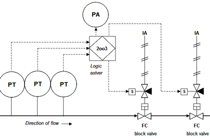
| Pressure, Flow Impulse line plugging | Common impulse lines of transmitters can affect the readings, resulting in a shutdown | Engineering to take care of using independent impulse lines for transmitters |
| Two transmitters are connected to one Annubar flow element | Plugging of one or more bores would influence the reading of both transmitters. | Design to take care of using separate flow elements as far as possible |
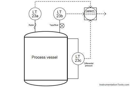
| Two transmitters are connected to one orifice (For Flow, Pressure & Differential pressure measurement) | a) Common impulse lines of transmitters can affect the readings, resulting in a shutdown. b) During Maintenance & flushing of transmitters may affect the healthy transmitter. c) Possibility of inadvertently performing maintenance on running instrument by maintenance personnel | It is always recommended to use 2 transmitters using an independent orifice. Note – Wherever the piping isometric doesn’t allow to install of separate orifice proper care to be done during maintenance. |
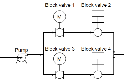
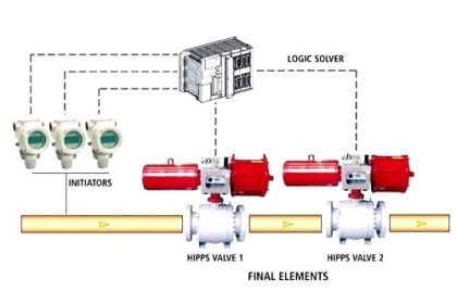
| Plugging prevents both final elements to reach the safe position | This is due to Instrument supply airline common connection plugging | Design independent impulse line, identify with proper tagging. For long standstill, valves Select the optimal valve type, move the valve frequently. Recommended to go with a Partial stroke testing device. |
| Changes in physical proprieties or ambient conditions influence both sensors (e.g. temperature, density, conductivity, Dielectric constant, etc.) | Improper provision of heating/cooling tubes or Electrical tracing. | Use alternative technologies or calculate influence and apply the correction factors as applicable. |
| The electrical signal of both elements is influenced (e.g. EMC, low supply voltage, others) | Power, Signal Cables running in the same tray. | Follow best wiring and installation practices, Electrical & Signal cabling to be laid in separate cable trays. |
| Loss of data communication | Signal interference | Adequate care with communication/Fiber optic/Ethernet cabling to be laid in separate cable trays/conduits. |
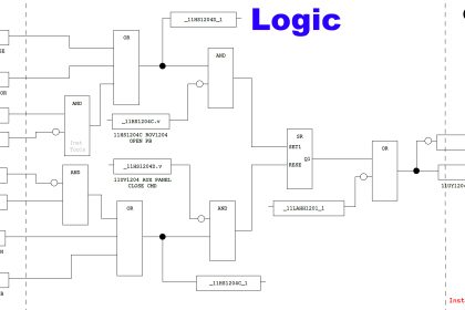
| Programming error propagated to two Independent Protection Layers | Control language / Ladder logic/ Function block diagram may be coded mistakenly with 2 different transmitter tags within one algorithm. | Use diverse architecture. Program coding to be verified thoroughly. |
| Two-wire transmitters require a minimum supply voltage at their terminals in order to work as required. | At times due to lengthy cables running from the control room to the field junction box | This value is provided in the datasheet from the manufacturer. For most transmitters, this minimum voltage is between 10 and 12 Volts. At average cable length, the power at the field instrument is still sufficient. |
| Electrical interference due to high voltage in the surrounding | Electrical interference may result in loss of signal | Proper care to be taken while installing the sensitive transmitters viz. Nuclear, Radar instruments – not to be so close to pumps/ compressors operating at high voltage |
Best Practices to Overcome CCF
- The best practices to avoid CCF shall consider the following:
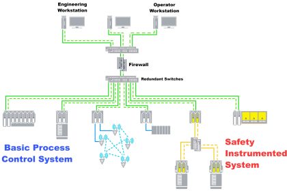
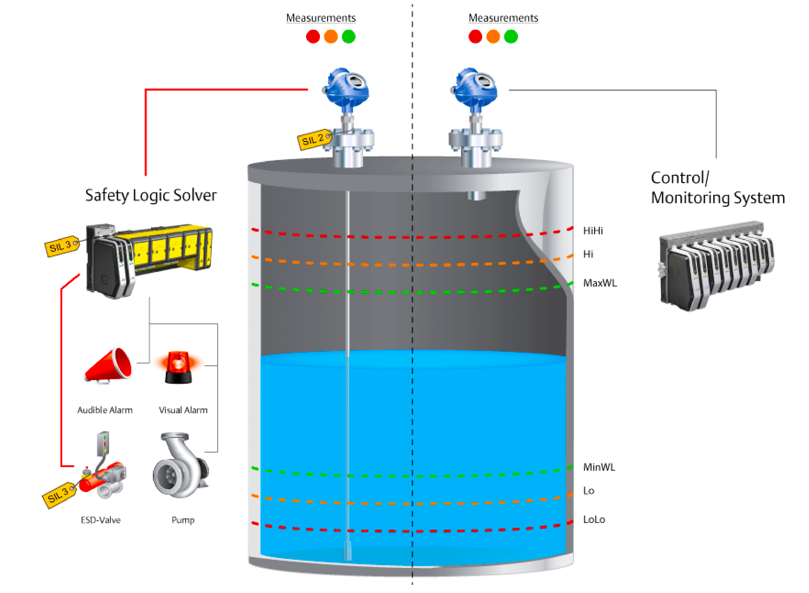
- Recommended to keep independency between protection layers (BPCS/SIS)
- Allow Diversity between protection layers (BPCS/SIS)
- Design to have a physical separation between different protection layers (BPCS/SIS)
- Adapt the techniques as listed in the above table to overcome common cause failures.
Beta factor
Beta factor indicates common cause susceptibility.
It is the fraction of the total failure rate that is attributed to a single cause in common with other typical installations in the group.
Common cause failures can occur due to many types of events, such as manufacturing defects in redundant devices, aging components, the severity of operating environment conditions, common process connections, and common support systems. These failures are referred to as dependent failures and are most commonly modeled using the beta factor method.
The value of the beta factor is selected based on prior use data in the operating environment. The prior use data can be for specific device technology.
Many plants use a beta factor between 1.0 and 5.0% when the devices are user approved for the application and good engineering practices are applied in the design and installation to minimize common cause failure.
The beta factor can be substantially higher if good engineering practices are not followed.
Reference:
IEC 61511: “Functional safety – Safety instrumented systems for the process industry sector”