Inst ToolsInst ToolsInst Tools
  • Courses
  • Automation
    • PLC
    • Control System
    • Safety System
    • Communication
    • Fire & Gas System
  • Instrumentation
    • Design
    • Pressure
    • Temperature
    • Flow
    • Level
    • Vibration
    • Analyzer
    • Control Valve
    • Switch
    • Calibration
    • Erection & Commissioning
  • Interview
    • Instrumentation
    • Electrical
    • Electronics
    • Practical
  • Q&A
    • Instrumentation
    • Control System
    • Electrical
    • Electronics
    • Analog Electronics
    • Digital Electronics
    • Power Electronics
    • Microprocessor
  • Request
Search
  • Books
  • Software
  • Projects
  • Process
  • Tools
  • Basics
  • Formula
  • Power Plant
  • Root Cause Analysis
  • Electrical Basics
  • Animation
  • Standards
  • 4-20 mA Course
  • Siemens PLC Course
Reading: Capacitance and Capacitive Reactance
Share
Font ResizerAa
Inst ToolsInst Tools
Font ResizerAa
  • Courses
  • Design
  • PLC
  • Interview
  • Control System
Search
  • Courses
  • Automation
    • PLC
    • Control System
    • Safety System
    • Communication
    • Fire & Gas System
  • Instrumentation
    • Design
    • Pressure
    • Temperature
    • Flow
    • Level
    • Vibration
    • Analyzer
    • Control Valve
    • Switch
    • Calibration
    • Erection & Commissioning
  • Interview
    • Instrumentation
    • Electrical
    • Electronics
    • Practical
  • Q&A
    • Instrumentation
    • Control System
    • Electrical
    • Electronics
    • Analog Electronics
    • Digital Electronics
    • Power Electronics
    • Microprocessor
  • Request
Follow US
All rights reserved. Reproduction in whole or in part without written permission is prohibited.
Inst Tools > Blog > Electrical Theory > Capacitance and Capacitive Reactance

Capacitance and Capacitive Reactance

Last updated: July 30, 2018 7:08 pm
Editorial Staff
Electrical Theory
No Comments
Share
4 Min Read
SHARE

Capacitors

The variation of an alternating voltage applied to a capacitor, the charge on the capacitor, and the current flowing through the capacitor are represented by Figure 3.

Current in a Capacitor

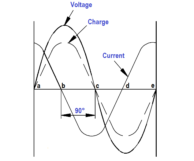
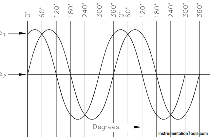
Figure 3 : Voltage, Charge, and Current in a Capacitor

The current flow in a circuit containing capacitance depends on the rate at which the voltage changes. The current flow in Figure 3 is greatest at points a, c, and e. At these points, the voltage is changing at its maximum rate (i.e., passing through zero).

Between points a and b, the voltage and charge are increasing, and the current flow is into the capacitor, but decreasing in value. At point b, the capacitor is fully charged, and the current is zero. From points b to c, the voltage and charge are decreasing as the capacitor discharges, and its current flows in a direction opposite to the voltage. From points c to d, the capacitor begins to charge in the opposite direction, and the voltage and current are again in the same direction.

At point d, the capacitor is fully charged, and the current flow is again zero. From points d to e, the capacitor discharges, and the flow of current is opposite to the voltage. Figure 3 shows the current leading the applied voltage by 90°. In any purely capacitive circuit, current leads applied voltage by 90°.

Capacitive Reactance

Capacitive reactance is the opposition by a capacitor or a capacitive circuit to the flow of current. The current flowing in a capacitive circuit is directly proportional to the capacitance and to the rate at which the applied voltage is changing. The rate at which the applied voltage is changing is determined by the frequency of the supply; therefore, if the frequency of the capacitance of a given circuit is increased, the current flow will increase.

It can also be said that if the frequency or capacitance is increased, the opposition to current flow decreases; therefore, capacitive reactance, which is the opposition to current flow, is inversely proportional to frequency and capacitance.

Capacitive reactance XC, is measured in ohms, as is inductive reactance.

The below Equation is a mathematical representation for capacitive reactance.
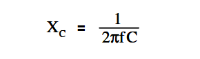
Capacitive Reactance

where

f = frequency (Hz)
π = ~3.14
C = capacitance (farads)

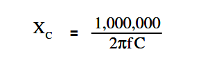
The below Equation is the mathematical representation of capacitive reactance when capacitance is expressed in microfarads (µF).

Capacitive Reactance equation

The below Equation is the mathematical representation for the current that flows in a circuit with only capacitive reactance.
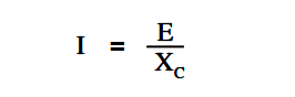
Capacitive Reactance and Current flow equation

where
I = effective current (A)
E = effective voltage across the capacitive reactance (V)
XC = capacitive reactance (Ω)

Example:

A 10µF capacitor is connected to a 120V, 60Hz power source (see Figure 4). Find the capacitive reactance and the current flowing in the circuit. Draw the phasor diagram.

Find the capacitive reactance and draw phasor diagram

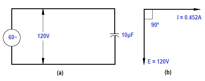
Figure 4 : Circuit and Phasor Diagram

Solution:

1. Capacitive reactance

Capacitive Reactance equation

XC =  1,000,000 / [ (2)(3.14)(60)(10) ]

XC =  1,000,000 / 3768 = 265.4 Ω

2. Current flowing in the circuit

Capacitive Reactance and Current flow equation

I = 120 / 265.4 = 0.452 amps

3. Phasor diagram showing current leading voltage by 90° is drawn in Figure 4b.

Don't Miss Our Updates
Be the first to get exclusive content straight to your email.
We promise not to spam you. You can unsubscribe at any time.
Invalid email address
You've successfully subscribed !

Continue Reading

D’Arsonval Meter Movement
How to Measure Specific Gravity of Battery
Synchronous Motors
Starting of DC Motors
Units of Electrical Measurement
Electrical Symbols
Share This Article
Facebook Whatsapp Whatsapp LinkedIn Copy Link
Share
Leave a Comment

Leave a Reply Cancel reply

Your email address will not be published. Required fields are marked *

Stay Connected

128.3kFollowersLike
69.1kFollowersFollow
210kSubscribersSubscribe
38kFollowersFollow

Categories

Explore More

Inductive Time Constant
Low Voltage Protection (LVP) and Low Voltage Release (LVR)
Transformer Current Ratio
DC Circuit Analysis Loop Equations
Electrical Diagrams and Schematics
Full-Wave Rectifier Circuit
Calculate Power in Parallel RL Circuit
Three Phase AC Generators

Keep Learning

AC Generator Operation

Losses in AC Generator

Series Parallel Circuit Analysis

Series – Parallel Circuit Analysis

Single Line Diagram

Single Line Diagram

Shunt-Wound DC Motor

Shunt-Wound Motor Operation

Left-Hand Rule for Generators

DC Generator Theory

Auto Transformer Schematic

Classification of Transformers

Induced EMF

Magnetic Circuits

Types of Batteries

Types of Batteries

Learn More

S84 - IEC 61511 Standard for Safety Instrumented Systems

S84 / IEC 61511 Standard for Safety Instrumented Systems

Pneumatic Transmitter

Pneumatic Level Transmitter Calibration Table

Chromatograph Principle

Basics of Chromatograph Operation

PLC Structured Text Program for Light Sequences via Timers

PLC Structured Text Program for Light Sequences via Timers

Benefits of SIMOCODE over Intelligent MCC

Benefits of SIMOCODE over Intelligent MCC

Electrical Machines Questions and Answers

Synchronous Machines Objective Questions

PLC Logic Example on Multiple Switches and Motors

PLC Logic Example on Multiple Switches and Motors

What is NEST loading in DCS

What is Nest Loading? – DCS and PLC Control Systems

Menu

  • About
  • Privacy Policy
  • Copyright

Quick Links

  • Learn PLC
  • Helping Hand
  • Part Time Job

YouTube Subscribe

Follow US
All rights reserved. Reproduction in whole or in part without written permission is prohibited.
Welcome Back!

Sign in to your account

Username or Email Address
Password

Lost your password?