Inst ToolsInst ToolsInst Tools
  • Courses
  • Automation
    • PLC
    • Control System
    • Safety System
    • Communication
    • Fire & Gas System
  • Instrumentation
    • Design
    • Pressure
    • Temperature
    • Flow
    • Level
    • Vibration
    • Analyzer
    • Control Valve
    • Switch
    • Calibration
    • Erection & Commissioning
  • Interview
    • Instrumentation
    • Electrical
    • Electronics
    • Practical
  • Q&A
    • Instrumentation
    • Control System
    • Electrical
    • Electronics
    • Analog Electronics
    • Digital Electronics
    • Power Electronics
    • Microprocessor
  • Request
Search
  • Books
  • Software
  • Projects
  • Process
  • Tools
  • Basics
  • Formula
  • Power Plant
  • Root Cause Analysis
  • Electrical Basics
  • Animation
  • Standards
  • 4-20 mA Course
  • Siemens PLC Course
Reading: D’Arsonval Meter Movement
Share
Font ResizerAa
Inst ToolsInst Tools
Font ResizerAa
  • Courses
  • Design
  • PLC
  • Interview
  • Control System
Search
  • Courses
  • Automation
    • PLC
    • Control System
    • Safety System
    • Communication
    • Fire & Gas System
  • Instrumentation
    • Design
    • Pressure
    • Temperature
    • Flow
    • Level
    • Vibration
    • Analyzer
    • Control Valve
    • Switch
    • Calibration
    • Erection & Commissioning
  • Interview
    • Instrumentation
    • Electrical
    • Electronics
    • Practical
  • Q&A
    • Instrumentation
    • Control System
    • Electrical
    • Electronics
    • Analog Electronics
    • Digital Electronics
    • Power Electronics
    • Microprocessor
  • Request
Follow US
All rights reserved. Reproduction in whole or in part without written permission is prohibited.
Inst Tools > Blog > Electrical Theory > D’Arsonval Meter Movement

D’Arsonval Meter Movement

Last updated: August 7, 2018 4:46 pm
Editorial Staff
Electrical Theory
No Comments
Share
2 Min Read
SHARE

The most commonly used sensing mechanism used in DC ammeters, voltmeters, and ohm meters is a current-sensing device called a D’Arsonval meter movement (Figure 1). The D’Arsonval movement is a DC moving coil-type movement in which an electromagnetic core is suspended between the poles of a permanent magnet.

D’Arsonval Movement

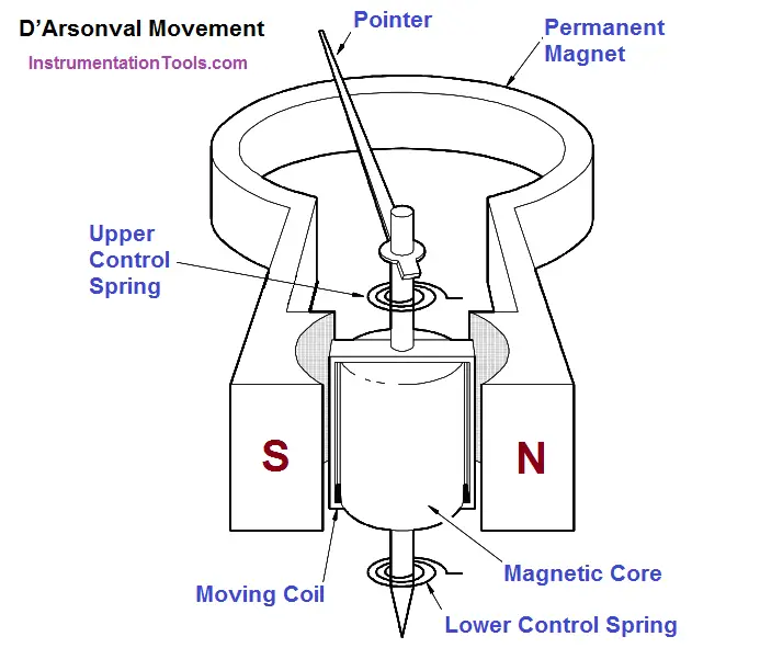
Figure 1 : D’Arsonval Meter Movement

The current measured is directed through the coils of the electromagnet so that the magnetic field produced by the current opposes the field of the permanent magnet and causes rotation of the core. The core is restrained by springs so that the needle will deflect or move in proportion to the current intensity.

The more current applied to the core, the stronger the opposing field, and the larger the deflection, up to the limit of the current capacity of the coil. When the current is interrupted, the opposing field collapses, and the needle is returned to zero by the restraining springs. The limit of the current that can be applied to this type movement is usually less than one milliampere.

A common variation of the D’Arsonval movement is the Weston movement, which uses essentially the same principle built to a more rugged construction by employing jeweled supports for the core and employing a heavier winding in the electromagnet. Remember that the D’Arsonval movement is a DC device and can only measure DC current or AC current rectified to DC.

Don't Miss Our Updates
Be the first to get exclusive content straight to your email.
We promise not to spam you. You can unsubscribe at any time.
Invalid email address
You've successfully subscribed !

Continue Reading

Series and Parallel Capacitors
Induction Motor
Circuit Breaker Control Circuit
Induction Motor Torque Versus Slip
What is a circuit breaker ?
Series – Parallel Circuit Analysis
Share This Article
Facebook Whatsapp Whatsapp LinkedIn Copy Link
Share
Leave a Comment

Leave a Reply Cancel reply

Your email address will not be published. Required fields are marked *

Stay Connected

128.3kFollowersLike
69.1kFollowersFollow
210kSubscribersSubscribe
38kFollowersFollow

Categories

Explore More

Inductive Time Constant
Block Diagram
Transformer Impedance Ratio
Starting of DC Motors
Resonance, Resonant Frequency, Series and Parallel Resonance
Battery Operation : Series and Parallel
Three Phase Wattmeter
AC Induction Motor Slip

Keep Learning

Potential Difference Across a Conductor Causes a Current to Flow

Conductor, Insulator, Resistor and Current Flow

Resistor Y and Delta Network Calculation

Y and Delta Resistor Network Calculations

Single Phase Motor Manual Controller

Motor Controllers

Transformer voltage and turns ratio

Transformer Voltage Ratio

Calculate Power in Series RC Circuit

Calculate Power in Series RC Circuit

AC Generator Nameplate Ratings

AC Generator Nameplate Ratings

Megger Circuit Diagram

Multimeter & Megger Principle

DC Machine

DC Generator Internal Losses

Learn More

pH Monitoring System Triggers an Alarm

pH Monitoring System Triggers an Alarm

Two Hand Press PLC

Two Hand Press Safety Control Circuit

How to Test a Motor using Megger

How to Test a Motor using Megger?

The Hardware Structure of DCS

DCS Applications and Hardware Structure of Plant Automation

What is a Magnetic Field

Difference Between Electric Field and Magnetic Field

Pressure Switch Construction

Basics of Pressure switches

fluid flow reversed through a Control Valve

What happens when Fluid Flow Reversed through Control Valve?

D’Arsonval Movement

D’Arsonval Movement

Menu

  • About
  • Privacy Policy
  • Copyright

Quick Links

  • Learn PLC
  • Helping Hand
  • Part Time Job

YouTube Subscribe

Follow US
All rights reserved. Reproduction in whole or in part without written permission is prohibited.
Welcome Back!

Sign in to your account

Username or Email Address
Password

Lost your password?