Inst ToolsInst ToolsInst Tools
  • Courses
  • Automation
    • PLC
    • Control System
    • Safety System
    • Communication
    • Fire & Gas System
  • Instrumentation
    • Design
    • Pressure
    • Temperature
    • Flow
    • Level
    • Vibration
    • Analyzer
    • Control Valve
    • Switch
    • Calibration
    • Erection & Commissioning
  • Interview
    • Instrumentation
    • Electrical
    • Electronics
    • Practical
  • Q&A
    • Instrumentation
    • Control System
    • Electrical
    • Electronics
    • Analog Electronics
    • Digital Electronics
    • Power Electronics
    • Microprocessor
  • Request
Search
  • Books
  • Software
  • Projects
  • Process
  • Tools
  • Basics
  • Formula
  • Power Plant
  • Root Cause Analysis
  • Electrical Basics
  • Animation
  • Standards
  • 4-20 mA Course
  • Siemens PLC Course
Reading: Ground Detector Principle
Share
Font ResizerAa
Inst ToolsInst Tools
Font ResizerAa
  • Courses
  • Design
  • PLC
  • Interview
  • Control System
Search
  • Courses
  • Automation
    • PLC
    • Control System
    • Safety System
    • Communication
    • Fire & Gas System
  • Instrumentation
    • Design
    • Pressure
    • Temperature
    • Flow
    • Level
    • Vibration
    • Analyzer
    • Control Valve
    • Switch
    • Calibration
    • Erection & Commissioning
  • Interview
    • Instrumentation
    • Electrical
    • Electronics
    • Practical
  • Q&A
    • Instrumentation
    • Control System
    • Electrical
    • Electronics
    • Analog Electronics
    • Digital Electronics
    • Power Electronics
    • Microprocessor
  • Request
Follow US
All rights reserved. Reproduction in whole or in part without written permission is prohibited.
Inst Tools > Blog > Electrical Theory > Ground Detector Principle

Ground Detector Principle

Last updated: August 13, 2018 12:47 pm
Editorial Staff
Electrical Theory
No Comments
Share
2 Min Read
SHARE

The ground detector is an instrument which is used to detect conductor insulation resistance to ground. An ohm meter, or a series of lights, can be used to detect the insulation strength of an ungrounded distribution system. Most power distribution systems in use today are of the grounded variety; however, some ungrounded systems still exist.

Ohm Meter Ground Detector Method

In the ohm meter method (below Figure), a DC voltage is applied to the conductor. If a leakage path exists between the conductor insulator and ground, a current will flow through the ground to the ohm meter proportional to the insulation resistance of the conductor.

Ohm Meter Ground Detector Principle

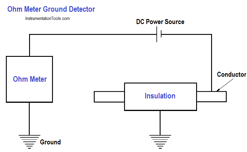
Figure : Simple Ohm Meter Ground Detector

Ground Detector Lamp Method

In the ground detector lamp method (below Figure), a set of three lamps connected through transformers to the system is used. To check for grounds, the switch is closed and the brilliance of the lamps is observed.

If the lamps are equally bright, no ground exists and all the lamps receive the same voltage. If any one lamp is dark, and the other two lamps are brighter, the phase in which the darkened lamp is in is grounded. In this case, the primary winding of the transformer is shorted to ground and receives no voltage.

Ground Detector Lamp Method Principle

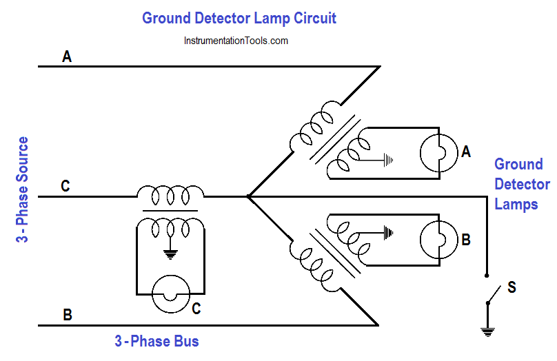
Figure : Ground Detector Lamp Circuit

Don't Miss Our Updates
Be the first to get exclusive content straight to your email.
We promise not to spam you. You can unsubscribe at any time.
Invalid email address
You've successfully subscribed !

Continue Reading

Circuit Breaker Control Circuit
High Voltage Circuit Breaker Principle
Y and Delta Resistor Network Calculations
4-Wire, Three-Phase Delta Wiring System
Power Factor Meter Principle
DC Motor Speed
Share This Article
Facebook Whatsapp Whatsapp LinkedIn Copy Link
Share
Leave a Comment

Leave a Reply Cancel reply

Your email address will not be published. Required fields are marked *

Stay Connected

128.3kFollowersLike
69.1kFollowersFollow
210kSubscribersSubscribe
38kFollowersFollow

Categories

Explore More

Methods of Producing Voltage (Electricity)
Discharge and Charging of Lead-Acid Battery
Impedance in RC Circuits
Transformer Impedance Ratio
Full-Wave Rectifier Circuit
Applying Kirchhoff’s Voltage Law
Simplified Formulas for Parallel Circuit Resistance Calculations
AC Generation

Keep Learning

3-Wire, Three-Phase Delta Wiring System

3-Wire, Three-Phase Delta Wiring System

Shunt-Wound DC Generator Principle

Shunt-Wound DC Generators

Three Phase AC Generators

Three Phase AC Generators

3φ AC Power Connections

Three Phase Systems

induction motor torque versus speed

Induction Motor Torque Versus Slip

Parallel RLC Circuit

Resonance, Resonant Frequency, Series and Parallel Resonance

Transformer Tap changer

Transformer Mutual Induction

AC Generator Nameplate Ratings

AC Generator Nameplate Ratings

Learn More

Best Software to Use to Improve Your Business

Best Software to Use in 2023 to Help Improve the Effectiveness of Your Business

Motor Star Delta Connections

How Motor Star Delta Starter Works ?

Pressure Gauge Datasheet

How to Fill up Instrument Datasheet? – Pressure Gauge Specifications & Standards

Troubleshooting a Biased Transistor

Troubleshooting a Biased Transistor

Instrumentation Engineering Standards Interview Questions & Answers

Electrical Machines Objective Questions & Answers

PLC Load Memory

What is Resources Tab in the Siemens PLC?

Power Plant Process Interlock for SA Fan I, & II

Boiler Safety and Process Interlocks – Power Plant Tutorials

Thermocouple Reference Junction

Thermocouple Working Principle

Menu

  • About
  • Privacy Policy
  • Copyright

Quick Links

  • Learn PLC
  • Helping Hand
  • Part Time Job

YouTube Subscribe

Follow US
All rights reserved. Reproduction in whole or in part without written permission is prohibited.
Welcome Back!

Sign in to your account

Username or Email Address
Password

Lost your password?