Inst ToolsInst ToolsInst Tools
  • Courses
  • Automation
    • PLC
    • Control System
    • Safety System
    • Communication
    • Fire & Gas System
  • Instrumentation
    • Design
    • Pressure
    • Temperature
    • Flow
    • Level
    • Vibration
    • Analyzer
    • Control Valve
    • Switch
    • Calibration
    • Erection & Commissioning
  • Interview
    • Instrumentation
    • Electrical
    • Electronics
    • Practical
  • Q&A
    • Instrumentation
    • Control System
    • Electrical
    • Electronics
    • Analog Electronics
    • Digital Electronics
    • Power Electronics
    • Microprocessor
  • Request
Search
  • Books
  • Software
  • Projects
  • Process
  • Tools
  • Basics
  • Formula
  • Power Plant
  • Root Cause Analysis
  • Electrical Basics
  • Animation
  • Standards
  • 4-20 mA Course
  • Siemens PLC Course
Reading: Inductance and Inductive Reactance
Share
Font ResizerAa
Inst ToolsInst Tools
Font ResizerAa
  • Courses
  • Design
  • PLC
  • Interview
  • Control System
Search
  • Courses
  • Automation
    • PLC
    • Control System
    • Safety System
    • Communication
    • Fire & Gas System
  • Instrumentation
    • Design
    • Pressure
    • Temperature
    • Flow
    • Level
    • Vibration
    • Analyzer
    • Control Valve
    • Switch
    • Calibration
    • Erection & Commissioning
  • Interview
    • Instrumentation
    • Electrical
    • Electronics
    • Practical
  • Q&A
    • Instrumentation
    • Control System
    • Electrical
    • Electronics
    • Analog Electronics
    • Digital Electronics
    • Power Electronics
    • Microprocessor
  • Request
Follow US
All rights reserved. Reproduction in whole or in part without written permission is prohibited.
Inst Tools > Blog > Electrical Theory > Inductance and Inductive Reactance

Inductance and Inductive Reactance

Last updated: July 30, 2018 1:33 pm
Editorial Staff
Electrical Theory
No Comments
Share
2 Min Read
SHARE

Inductance

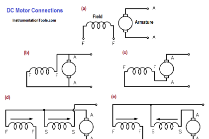
Any device relying on magnetism or magnetic fields to operate is a form of inductor. Motors, generators, transformers, and coils are inductors. The use of an inductor in a circuit can cause current and voltage to become out-of-phase and inefficient unless corrected.

Inductive Reactance

In an inductive AC circuit, the current is continually changing and is continuously inducing an EMF. Because this EMF opposes the continuous change in the flowing current, its effect is measured in ohms. This opposition of the inductance to the flow of an alternating current is called inductive reactance (XL).

The below Equation is the mathematical representation of the current flowing in a circuit that contains only inductive reactance.

inductive reactance current equation

where

I = effective current (A)
XL= inductive reactance (Ω)
E = effective voltage across the reactance (V)

The value of XL in any circuit is dependent on the inductance of the circuit and on the rate at which the current is changing through the circuit. This rate of change depends on the frequency of the applied voltage.

The below Equation is the mathematical representation for XL.

XL = 2πfL

where
π = ~3.14
f = frequency (Hertz)
L = inductance (Henries)

The magnitude of an induced EMF in a circuit depends on how fast the flux that links the circuit is changing. In the case of self-induced EMF (such as in a coil), a counter EMF is induced in the coil due to a change in current and flux in the coil. This CEMF (counter EMF) opposes any change in current, and its value at any time will depend on the rate at which the current and flux are changing at that time. In a purely inductive circuit, the resistance is negligible in comparison to the inductive reactance. The voltage applied to the circuit must always be equal and opposite to the EMF of self-induction.

Don't Miss Our Updates
Be the first to get exclusive content straight to your email.
We promise not to spam you. You can unsubscribe at any time.
Invalid email address
You've successfully subscribed !

Continue Reading

Wattmeter
What is Synchroscope ?
Transformer Efficiency
Transformer Current Ratio
DC Motor Theory
DC Motor Speed
Share This Article
Facebook Whatsapp Whatsapp LinkedIn Copy Link
Share
Leave a Comment

Leave a Reply Cancel reply

Your email address will not be published. Required fields are marked *

Stay Connected

128.3kFollowersLike
69.1kFollowersFollow
210kSubscribersSubscribe
38kFollowersFollow

Categories

Explore More

Three Phase Transformer Connections
Impedance in RC Circuits
Classification of Transformers
Batteries
Ampere Hour Meter
Electro-Dynamo Meter Movement
Series and Parallel Capacitors
Parallel Circuit

Keep Learning

Induced EMF

Magnetic Circuits

Unbalanced 3 Phase Loads

Unbalanced 3 Phase Loads

Resistor Y and Delta Network Calculation

Y and Delta Resistor Network Calculations

AC Generator Operation

Losses in AC Generator

Lead Acid Battery charge

Discharge and Charging of Lead-Acid Battery

D’Arsonval Movement

D’Arsonval Meter Movement

Left-Hand Rule for Generators

DC Generator Theory

Electrical Component Symbols

Electrical Diagrams and Schematics

Learn More

Use PLC Flags as Integrity Checks

#4 PLC Best Practices – Use PLC Flags as Integrity Checks

0 to 10 mA Current Loop

What is Live Zero in 4-20 mA Current Loop?

Types of Pressure Measuring Scales

Types of Pressure Measuring Scales

PID Simulator

PID Simulator Download

Electrical Machines Questions and Answers

Inductive Impedance Questions

Characteristics of Level Measurement Technologies

Identify Characteristics of Level Measurement Technologies

Thermocouple measurement and reference junction temperatures

Thermocouple Measurement and Reference Junction Temperatures

Applications of Variable Frequency Drive (VFD)

Menu

  • About
  • Privacy Policy
  • Copyright

Quick Links

  • Learn PLC
  • Helping Hand
  • Part Time Job

YouTube Subscribe

Follow US
All rights reserved. Reproduction in whole or in part without written permission is prohibited.
Welcome Back!

Sign in to your account

Username or Email Address
Password

Lost your password?