Inst ToolsInst ToolsInst Tools
  • Courses
  • Automation
    • PLC
    • Control System
    • Safety System
    • Communication
    • Fire & Gas System
  • Instrumentation
    • Design
    • Pressure
    • Temperature
    • Flow
    • Level
    • Vibration
    • Analyzer
    • Control Valve
    • Switch
    • Calibration
    • Erection & Commissioning
  • Interview
    • Instrumentation
    • Electrical
    • Electronics
    • Practical
  • Q&A
    • Instrumentation
    • Control System
    • Electrical
    • Electronics
    • Analog Electronics
    • Digital Electronics
    • Power Electronics
    • Microprocessor
Search
  • Books
  • Software
  • Projects
  • Process
  • Tools
  • Basics
  • Formula
  • Power Plant
  • Root Cause Analysis
  • Electrical Basics
  • Animation
  • Standards
  • 4-20 mA Course
  • Siemens PLC Course
Reading: Ammeter
Share
Notification Show More
Font ResizerAa
Inst ToolsInst Tools
Font ResizerAa
  • Courses
  • Design
  • PLC
  • Interview
  • Control System
Search
  • Courses
  • Automation
    • PLC
    • Control System
    • Safety System
    • Communication
    • Fire & Gas System
  • Instrumentation
    • Design
    • Pressure
    • Temperature
    • Flow
    • Level
    • Vibration
    • Analyzer
    • Control Valve
    • Switch
    • Calibration
    • Erection & Commissioning
  • Interview
    • Instrumentation
    • Electrical
    • Electronics
    • Practical
  • Q&A
    • Instrumentation
    • Control System
    • Electrical
    • Electronics
    • Analog Electronics
    • Digital Electronics
    • Power Electronics
    • Microprocessor
Follow US
All rights reserved. Reproduction in whole or in part without written permission is prohibited.
Inst Tools > Blog > Electrical Theory > Ammeter

Ammeter

Last updated: August 7, 2018 11:47 pm
Editorial Staff
Electrical Theory
No Comments
Share
4 Min Read
SHARE

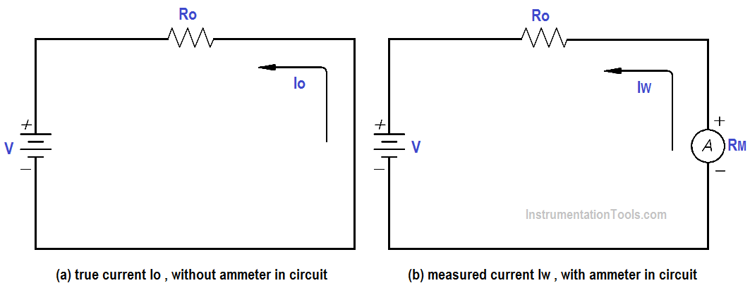
The ammeter measures electric current. It may be calibrated in amperes, milliamperes, or microamperes. In order to measure current, the ammeter must be placed in series with the circuit to be tested (as shown in below Figure 1).
Ammeter

Figure 1 : Ammeter

When an ammeter is placed in series with a circuit, it will increase the resistance of that circuit by an amount equal to the internal resistance of the meter Rm.

The below Equation is the mathematical representation of the current without the meter installed.

Ammeter Current Formula

The below Equation is the mathematical representation of the current with the meter installed in the circuit.

Ammeter Current Formula - 1

The accuracy of the ammeter KA is the ratio of the current when the meter is in the circuit, Iw , to the current with the meter out of the circuit, Io .

The below Equation is the mathematical representation for solving for the accuracy of the ammeter (KA).

accuracy of the ammeter

By substitution laws, The below Equation is a mathematical representation of the accuracy using circuit resistance.

Ammeter Accuracy Formula

The percent loading error is that percent of error due to loading effects that result from the added resistance of the meter.

The below Equation is a mathematical representation of the percent loading error.

% loading error = (1 – KA )(100 %)

A second error which occurs in an ammeter is calibration error. Calibration error is an error that occurs due to inaccurately marked meter faces. Typical values of calibration error in terms of full scale current are about 3 percent.

Example:

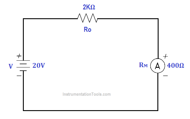
An ammeter, with a 10 mA full scale deflection and an internal resistance of 400 Ω, is placed in a circuit with a 20 V power source and a 2KΩ resistor.
Ammeter Accuracy Calculation

Figure 2 : Ammeter Accuracy

Find:

  1. accuracy
  2. %loading error
  3. true current
  4. measured current

Calculate Accuracy

KA = R / (Ro + Rm)

KA = 2000/(2000 + 2000)

KA = 0.833 or 83.3%

Calculate %loading error

% loading error = (1 – KA )(100 %)

% loading error = (1 – 0.833) (100%)

% loading error = 16.7 %

Calculate true current

Ammeter Current Formula

Io = 20 / 2000

Io = 0.01 A or 10mA

Calculate measured current

Ammeter Current Formula - 1

Iw = 20 / (2000 + 400)

Iw = 8.33 mA

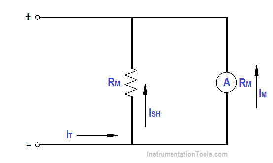
An ammeter with a full scale Im can be shunted with a resistor RSH in order to measure currents in excess of Im (as shown in Figure). The reason for shunting an ammeter is to extend the range of the ammeter and, thereby, measure currents higher than the original full scale value.
Ammeter with Shunt

Figure 3 : Ammeter with Shunt

By Kirchhoff’s current law,

ISH = IT – Im

Since the voltage across the shunt must be equal to the voltage across the ammeter, shunt resistance is calculated as follows:
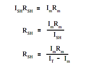
Ammeter Shunt Resistance

Therefore, the input resistance of a shunted ammeter is related to the meter and shunt resistance. The below Equation is a mathematical representation of this relationship.

NOTE: When computing accuracy for a shunted ammeter, use Rm‘ in place of Rm

Ammeter Current Formula - 2

The below Equation is a mathematical representation of the relationship between input voltage and current to the ammeter and the value of input resistance.

Ammeter Current Formula - 3

Example:

An ammeter, with a 100 Ω meter resistance and a full scale deflection current of 4 mA, is to be shunted to measure currents from 1 to 20 mA.

Find:

  1. RSH
  2. Rm‘

Solution :

RSH = (Im Rm ) / ( Im – Rm )

RSH = 4 x 100 / (20-4)

RSH = 25Ω

Rm‘ = (Im Rm ) /  IT

Rm‘ = 4×100 / 20

Rm‘ = 20Ω
Don't Miss Our Updates
Be the first to get exclusive content straight to your email.
We promise not to spam you. You can unsubscribe at any time.
Invalid email address
You've successfully subscribed !

Continue Reading

Batteries Theory
Voltage and Current Phase Relationships in an Inductive Circuit
Reading Electrical Schematics
Electrical Diagrams and Schematics
Types of AC Generators
Schematic Diagram
Share This Article
Facebook Whatsapp Whatsapp LinkedIn Copy Link
Share
Leave a Comment

Leave a Reply Cancel reply

Your email address will not be published. Required fields are marked *

Stay Connected

128.3kFollowersLike
69.1kFollowersFollow
208kSubscribersSubscribe
38kFollowersFollow

Categories

Explore More

Resistance in Parallel Circuits
Voltage Polarity and Current Direction
Transformer Turns Ratio
What is a circuit breaker ?
Induction Motor
Starting of DC Motors
Capacitance and Capacitive Reactance
DC Generator

Keep Learning

Wiring Diagram

Wiring Diagram

Single Line Diagram

Single Line Diagram

Types of Batteries

Types of Batteries

Capacitor Principle

Capacitor

Inductor Principle

Inductor

Transformer Tap changer

Transformer Mutual Induction

Power Triangle

Power Triangle

Calculate Power in Parallel RL Circuit

Calculate Power in Parallel RL Circuit

Learn More

GATE Instrumentation Questions and Answers

GATE Instrumentation Questions and Answers

DP transmitter Elevated 10 Feet above the Vessel

DP transmitter Elevated 10 Feet above the Vessel

How to Test a Pressure Switch ?

How to Test a Pressure Switch ?

Hard-Wired Control Logic for the Pressure Alarm

Hard-Wired Control Logic for the Pressure Alarm

importance-of-device-diagnostics

Importance of Device Diagnostics

High-Speed Inputs in PLC

What are High-Speed Inputs in PLC?

Nuclear Magnetic Resonance Spectrometer Questions and Answers

Nuclear Magnetic Resonance Spectrometer Questions & Answers

PLC Totalizer

PLC Program for Flow Totalizer

Follow US
All rights reserved. Reproduction in whole or in part without written permission is prohibited.
Welcome Back!

Sign in to your account

Username or Email Address
Password

Lost your password?