Inst ToolsInst ToolsInst Tools
  • Courses
  • Automation
    • PLC
    • Control System
    • Safety System
    • Communication
    • Fire & Gas System
  • Instrumentation
    • Design
    • Pressure
    • Temperature
    • Flow
    • Level
    • Vibration
    • Analyzer
    • Control Valve
    • Switch
    • Calibration
    • Erection & Commissioning
  • Interview
    • Instrumentation
    • Electrical
    • Electronics
    • Practical
  • Q&A
    • Instrumentation
    • Control System
    • Electrical
    • Electronics
    • Analog Electronics
    • Digital Electronics
    • Power Electronics
    • Microprocessor
  • Request
Search
  • Books
  • Software
  • Projects
  • Process
  • Tools
  • Basics
  • Formula
  • Power Plant
  • Root Cause Analysis
  • Electrical Basics
  • Animation
  • Standards
  • 4-20 mA Course
  • Siemens PLC Course
Reading: How to Calibrate Oxygen Analyzer? – O2 Sensor Testing Procedure
Share
Font ResizerAa
Inst ToolsInst Tools
Font ResizerAa
  • Courses
  • Design
  • PLC
  • Interview
  • Control System
Search
  • Courses
  • Automation
    • PLC
    • Control System
    • Safety System
    • Communication
    • Fire & Gas System
  • Instrumentation
    • Design
    • Pressure
    • Temperature
    • Flow
    • Level
    • Vibration
    • Analyzer
    • Control Valve
    • Switch
    • Calibration
    • Erection & Commissioning
  • Interview
    • Instrumentation
    • Electrical
    • Electronics
    • Practical
  • Q&A
    • Instrumentation
    • Control System
    • Electrical
    • Electronics
    • Analog Electronics
    • Digital Electronics
    • Power Electronics
    • Microprocessor
  • Request
Follow US
All rights reserved. Reproduction in whole or in part without written permission is prohibited.
Inst Tools > Blog > Analyzers > How to Calibrate Oxygen Analyzer? – O2 Sensor Testing Procedure

How to Calibrate Oxygen Analyzer? – O2 Sensor Testing Procedure

Let us see how to calibrate oxygen analyzer which is having a electrochemical cell. Also learn O2 sensor testing procedure.

Last updated: December 1, 2023 10:05 am
Editorial Staff
Analyzers Calibration
No Comments
Share
5 Min Read
SHARE

An oxygen analyzer is used in almost all industries for measuring oxygen content in the gas sample. Especially, in utility plants, an oxygen analyzer is used to measure oxygen content in the process industry.

Contents
Oxygen AnalyzerCalibration ToolsHow to Calibrate an Oxygen Analyzer?

For example, in the instrument Air dryer and N2 plant, we generally use an O2 sensor, which is an important analyzer.
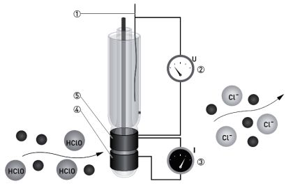
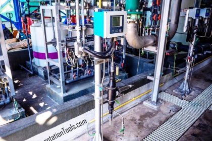
Oxygen Analyzer

Let us see how to calibrate this oxygen analyzer. Today in this article we will have a look at the calibration of an oxygen analyzer with having electrochemical cell as a sensor.

Calibration of other types of oxygen sensors is also almost the same with minor changes in procedure.

Technologies for Oxygen Gas Measurement

What are the necessary tools and tackles required for the calibration of oxygen analyzers?

The calibration of analyzers is always a bit different from other field instruments. Because in this process, we need calibration gas.

Below mentioned tools and tackles are necessary for the calibration of the oxygen analyzer
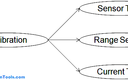
Calibration Tools

The tools and tackles used for calibrating are:

  1. Sample gas cylinder corresponding to 0 ppm of oxygen (pure nitrogen)
  2. Sample gas cylinder corresponding to the value of the upper range value of the analyzer (we took 5 ppm as the upper range value)
  3. Gas flow regulator for both cylinders
  4. Snoop liquid leak detector (or any other leak detector solution)

Always make sure that the gas cylinder’s validity is not over. Because this can lead to inaccurate calibrations.

How to Calibrate an Oxygen Analyzer?

Calibration of the oxygen analyzer can be done by following below-mentioned steps:

  1. Take permit to work corresponding to the analyzer on which job is to be done
  2. Bypass the interlock present for the tag on which the job is to be done (if available). An interlock bypass procedure needs to be followed for the bypassing interlock.
  3. Inform the operation department about the job and also other plants that are monitoring this oxygen analyzer’s value.
  4. Isolate the sample to the oxygen analyzer.
  5. Now, connect the sample gas cylinder corresponding to 0 ppm to the analyzer. Before routing the cylinder’s gas directly to the analyzer, vent some sample by opening the tube near the rotameter for flow measurement such that some sample goes to the rotameter as well as some flow gets vented. This will flush the line and remove oxygen as well as other gases present in the tube which we have connected. Now, establish flow as per manufacturer instructions to the analyzer. Wait for 5-10 minutes. If the value has become stable at one point, note down that value else wait for some more time so that the value gets stable.
  6. Calculate the error%. If the error % is more than acceptable then go for calibration. Go to the settings of the analyzer and apply Zero Calibrate. The analyzer will now start showing 0 ppm.
  7. Isolate this 0 ppm sample to the analyzer.
  8. Now connect the sample gas cylinder corresponding to 5 ppm to the analyzer and repeat the same procedure for flushing. Now establish the proper flow as per manufacturer instructions and wait for some time so that the value gets stable.
  9. Calculate the error%. If the error % is more than acceptable then go for calibration. If only the span is disturbed then go to settings and apply Span Calibrate and enter the value as 5 ppm. Now the analyzer will start showing 5 ppm.
  10. Now go to step 5 and repeat the steps until you get the desired results.
  11. If still, the analyzer is still not responding properly, then replace the electrochemical cell and calibrate it again.
  12. Take the analyzer in line after completing the job and see the response of the analyzer for 1-2 hours.
  13. Restore the interlocks which have been bypassed before the job.
  14. Close the permit and inform concerned people about the closure of the job.

If you liked this article, then please subscribe to our YouTube Channel for Electrical, Electronics, Instrumentation, PLC, and SCADA video tutorials.

You can also follow us on Facebook and Twitter to receive daily updates.

Read Next:

  • Oxygen Gas Measurement
  • Carbon Dioxide in Flue Gas
  • pH Analyzer Common Problems
  • Troubleshooting Oxygen Analyzer
  • Cell Constant in Conductivity Analyzer
Don't Miss Our Updates
Be the first to get exclusive content straight to your email.
We promise not to spam you. You can unsubscribe at any time.
Invalid email address
You've successfully subscribed !

Continue Reading

Types of Calibration
Non-Dispersive Analyzers
Ammonia Gas Detector Working Principle and Calibration
Falling Ball Viscometer Principle
Basics of Suspended Particulate Matter (SPM) Analyzers
Pressure Gauge Calibration according to Standard DKD-R-6-1
Share This Article
Facebook Whatsapp Whatsapp LinkedIn Copy Link
Share
Leave a Comment

Leave a Reply Cancel reply

Your email address will not be published. Required fields are marked *

Stay Connected

128.3kFollowersLike
69.1kFollowersFollow
210kSubscribersSubscribe
38kFollowersFollow

Categories

Explore More

Foundation Fieldbus Transmitter Calibration
Motor Operated Valve Functional Testing
Conductivity Analyzers Interview Questions & Answers
Difference between Calibration and Ranging
Dissolved Oxygen Analyzer Working Principle
Capacitance Level Switch Calibration
Multiphase Flow Meter Calibration Procedure
Ammonia Analyzer Principle

Keep Learning

Single Position Calibration of Temperature Bath

Single Position Calibration of Temperature Bath

How to Calibrate Load Cells

How to Calibrate Load Cells in Weighing Applications?

Reliability Centered Maintenance (RCM)

What is Reliability Centered Maintenance? (RCM)

NIST Traceability

NIST Traceability

Turbidity Analyzer Working Principle

Turbidity Analyzer Working Principle

Self Actuated Pressure Control Valve Functional Testing

Self Actuated Pressure Control Valve Functional Testing

toroidal conductivity probe principle

Electrodeless Conductivity Probes Principle

Ultrasonic Level Transmitters Installation

Ultrasonic Level Transmitter Principle, Limitations, Calibration and configuration

Learn More

Is it Possible to Measure liquid-liquid Level Interface using Float

Is it Possible to Measure Liquid-Liquid Level Interface using Float?

Sample Schematic Template for Systems Architecture Diagram

Design Document for Project Systems Architecture

Helix and Spiral Tubes - Pressure Sensor

Helix and Spiral Tubes – Pressure Sensor

PIN Diode Working Principle

PIN Diode Working Principle

McLeod Gauge Working Principle

McLeod Gauge Working Principle

Partial Stroke Testing Device (PSD) in SIS Final Control Element

Partial Stroke Testing Device (PSD) in SIS Final Control Element

Innovative Segment Orifice

Stuck Segment Orifice Dimensions Calculations

LRV and URV of PT for Extreme Limits of Empty and Full

LRV and URV of PT for Extreme Limits of Empty and Full

Menu

  • About
  • Privacy Policy
  • Copyright

Quick Links

  • Learn PLC
  • Helping Hand
  • Part Time Job

YouTube Subscribe

Follow US
All rights reserved. Reproduction in whole or in part without written permission is prohibited.
Welcome Back!

Sign in to your account

Username or Email Address
Password

Lost your password?