Fieldbus transmitter ranging application, this time a differential pressure transmitter sensing pressure dropped across an orifice plate in order to infer the rate of flow for fluid inside the pipe. The transmitter senses small amounts of pressure difference (expressed in a unit of pressure called inches water column), but what we want it to report to the Fieldbus network is an actual flow rate in gallons per minute.
If we happen to know that this orifice plate produces a pressure drop of 125 inches water column (125 ”WC) at a flow rate of 350 gallons per minute (350 GPM), we could set up the scaling parameters as shown:
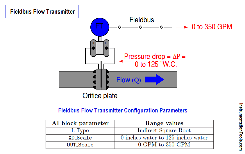
Note the use of the “indirect square root ” L_Type parameter value instead of just “indirect” as we used in the ethanol tank example. The square root function is necessary in this application because the relationship between differential pressure (∆P) and flow rate (Q) through an orifice is nonlinear, as described by the following formula:

This particular non-linearity is unique to pressure-based measurements of fluid flow, and does not find application in any other form of process measurement.
As before, though, we see a common theme with the XD_Scale and OUT_Scale parameter ranges: we set the XD_Scale parameter to the physical range of measurement directly sensed by the transducer, we set the OUT_Scale parameter to the corresponding range of measurement we wish the transmitter to report to the rest of the control system, and we set L_Type to “indirect” to enable this translation from one range to another.
Also Read : SMART Transmitter Calibration