Inst ToolsInst ToolsInst Tools
  • Courses
  • Automation
    • PLC
    • Control System
    • Safety System
    • Communication
    • Fire & Gas System
  • Instrumentation
    • Design
    • Pressure
    • Temperature
    • Flow
    • Level
    • Vibration
    • Analyzer
    • Control Valve
    • Switch
    • Calibration
    • Erection & Commissioning
  • Interview
    • Instrumentation
    • Electrical
    • Electronics
    • Practical
  • Q&A
    • Instrumentation
    • Control System
    • Electrical
    • Electronics
    • Analog Electronics
    • Digital Electronics
    • Power Electronics
    • Microprocessor
  • Request
Search
  • Books
  • Software
  • Projects
  • Process
  • Tools
  • Basics
  • Formula
  • Power Plant
  • Root Cause Analysis
  • Electrical Basics
  • Animation
  • Standards
  • 4-20 mA Course
  • Siemens PLC Course
Reading: Ammonia Gas Detector Working Principle and Calibration
Share
Notification Show More
Font ResizerAa
Inst ToolsInst Tools
Font ResizerAa
  • Courses
  • Design
  • PLC
  • Interview
  • Control System
Search
  • Courses
  • Automation
    • PLC
    • Control System
    • Safety System
    • Communication
    • Fire & Gas System
  • Instrumentation
    • Design
    • Pressure
    • Temperature
    • Flow
    • Level
    • Vibration
    • Analyzer
    • Control Valve
    • Switch
    • Calibration
    • Erection & Commissioning
  • Interview
    • Instrumentation
    • Electrical
    • Electronics
    • Practical
  • Q&A
    • Instrumentation
    • Control System
    • Electrical
    • Electronics
    • Analog Electronics
    • Digital Electronics
    • Power Electronics
    • Microprocessor
  • Request
Follow US
All rights reserved. Reproduction in whole or in part without written permission is prohibited.
Inst Tools > Blog > Analyzers > Ammonia Gas Detector Working Principle and Calibration

Ammonia Gas Detector Working Principle and Calibration

Last updated: July 20, 2019 11:26 am
Editorial Staff
Analyzers Calibration
No Comments
Share
5 Min Read
SHARE

Ammonia gas detector working principle and calibration. (Make: Dragger Model : Polytron 5100)

Gas detector is a very important safety device for any chemical plant. Its can give information in any small leak from any pipelines and with early action we can save any incident in plant.

In any chemical plant generally we use four types detector:

  1. Hydrocarbon Detector
  2. CO detector
  3. NH3 detector
  4. Chlorine detector

Here we discussed about Ammonia detector.

Principle :

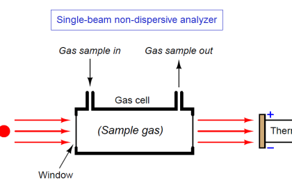
Ammonia detector works on electrochemical principle. Electrochemical sensors are electrochemical measuring transducers for measuring the partial pressure of gases under atmospheric conditions. The ambient air being monitored diffuses through a membrane into the liquid electrolyte in the sensor. The electrolyte contains a measuring electrode, a counter-electrode and a reference electrode. An electronic potentiostatic circuit ensures a constant electrical voltage between the measuring electrode and reference electrode.

Voltage, electrolyte and electrode material are selected to suit the gas being monitored so that it is transformed electrochemically on the measuring electrode and a current flows through the sensor. This current is proportional to the gas concentration. At the same time, oxygen from the ambient air reacts at the counter-electrode electrochemically. The current flowing through the sensor is amplified electronically, digitized and corrected for several parameters (e.g. the ambient temperature). The resulting measured value is given as an analog, 4-20 mA signal.

Gas Detector Internal Circuit

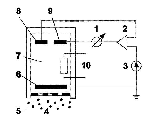
Gas Detector Parts :

  1. Meter
  2. Potentiostat
  3. Direct current supply
  4. Measured gas
  5. Membrane
  6. Measuring electrode
  7. Electrolyte
  8. Reference electrode
  9. Counter electrode
  10. Temperature sensor

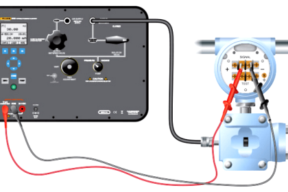
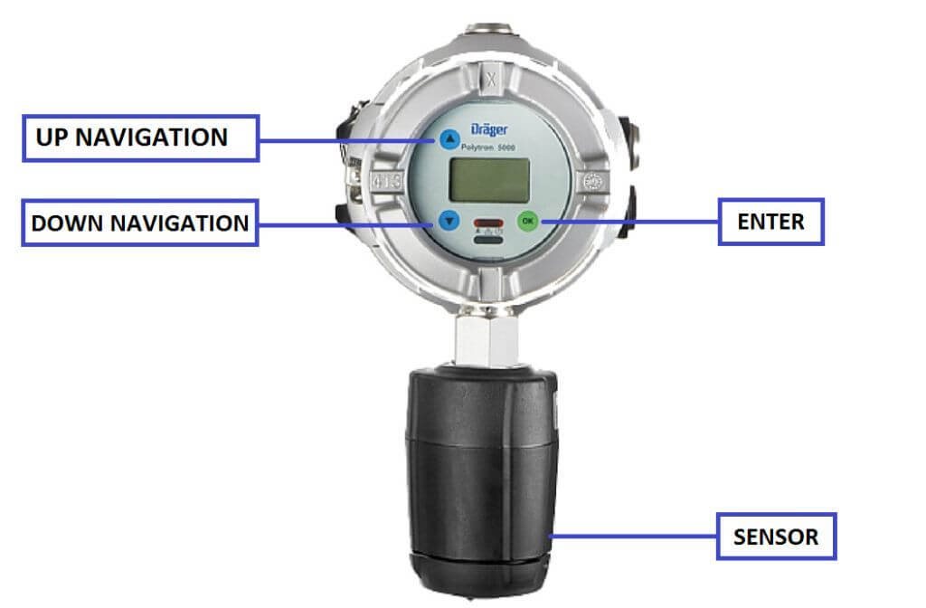
Configuration of Gas Detector:

Gas detector can be used as a two wire or as three wire device.

Connect the gas detector wiring as per your requirement & Power ON the detector. Display shows a start up timer.

Wait for the timer to complete and then press down navigation and go to FSD for Span range.

Ammonia Gas Detector Calibration

Calibration of Gas Detector:

For calibration we use N2 gas for zero calibration and 90 PPM ammonia cylinder for span gas .

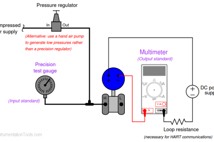
Typical Calibration Setup : 
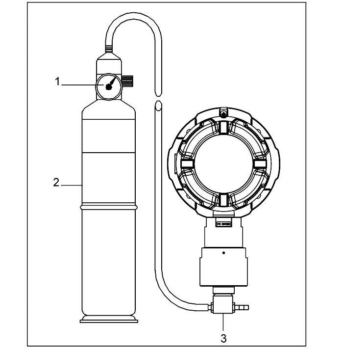
Gas Detector Calibration Setup

Parts :

  1. Regulator
  2. Calibration gas cylinders ( Zero Gas Cylinder & Span Gas Cylinder  )
  3. Calibration adapter

For zero calibration

  1. Connect the regulator with N2 cylinder adapter to detector then adjust the flow to 0.5 l/min
  2. Press down navigation key for 5 sec its showing -0- Adj.
  3. Tap [OK].
  4. The display will show the current value blinking.
  5. Wait for the value to stabilize.
  6. Use [UP] / [DOWN] navigation to adjust the value to 0.
  7. Enter [OK] then detector return to main menu.
  8. Turn off gas flow and remove the calibration adapter from the sensor or disconnect tubing.

Note : Ambient air can be used to zero the sensor instead of nitrogen or Zero Air if the area is known to be free of the target gas or any gas to which the sensor may be cross-sensitive. In this case, no cylinder or calibration adapter is needed for the zero calibration.

For span calibration

  1. Connect the regulator with 90 PPM ammonia cylinder adapter to detector then adjust the flow to 0.5 l/min
  2. Press down navigation key for 5 sec its showing -0- Adj. press down its showing SPn Adj
  3. Tap [OK].
  4. The display will show the current value blinking.
  5. Wait for the value to stabilize.
  6. Use [UP] / [DOWN] navigation to adjust the value (As mention on cylinder certificate, means span cylinder gas concentration).
  7. Enter [OK] then detector return to main menu.
  8. Turn off gas flow and remove the calibration adapter from the sensor or disconnect tubing.

General Preventive Maintenance : In every 6 months once, carry out the calibration of gas detector.

Reference : Drager Manual

Article by :
Ashish Agrawal
Don't Miss Our Updates
Be the first to get exclusive content straight to your email.
We promise not to spam you. You can unsubscribe at any time.
Invalid email address
You've successfully subscribed !

Continue Reading

Calibration MCQ – Terminology and Glossary Questions
Differential Pressure Sensors Calibration Procedure
Two Electrode Conductivity Probes Principle
Dew Point Meter Principle
Questions and Answers on Gas
Difference Between Absolute and Relative Humidity
Share This Article
Facebook Whatsapp Whatsapp LinkedIn Copy Link
Share
Leave a Comment

Leave a Reply Cancel reply

Your email address will not be published. Required fields are marked *

Stay Connected

128.3kFollowersLike
69.1kFollowersFollow
210kSubscribersSubscribe
38kFollowersFollow

Categories

Explore More

Basics of Chromatograph Operation
Installation and Calibration of Pressure Transmitter
Calibrating Level Transmitter with Remote Seals
Calibration and Preventative Maintenance Procedures
Oxygen (O2) Measurement in Flue Gas
Gas Analyzer Sampling System
Measuring Gases Concentration in Chromatograph
The Principle of Dead Weight Pressure Tester

Keep Learning

Oil in Water Analyzer Principle

Oil in Water Analyzer Working Principle

Humidity sensor Working Principle

Humidity Sensor Working Principle

RTD Testing Methods

RTD Testing Methods in Calibration Laboratory

process chemical analyzer calibration

Automated Calibration

Pressure Gauge Calibration Procedure

Motor Operated Valve Functional Testing

Motor Operated Valve Functional Testing

How to Test a Pressure Switch ?

How to Test a Pressure Switch ?

Sox Nox Analyzer

Sox Nox Analyzer

Learn More

Advantages of Star and Delta Systems

Advantages of Star and Delta Systems

Final Year Engineering Projects

Final Year Engineering Projects for ECE, EEE and EIE Students

Download Free Robotics Software

Step by Step Guidelines to Download Free Robotics Software

Statement List (STL) to Find Highest Value in the Data Block

Statement List (STL) to Find Highest Value

Power Electronics Objective Questions

Single-Phase Half Wave AC-DC Converter MCQ

PLC based Door Open and Closing System

PLC based Door Open and Closing System

Programmable Logic Controller Practice Tests

Programmable Logic Controller Practice Tests

Feedback control loop - 2

Feedback Control Principle

Menu

  • About
  • Privacy Policy
  • Copyright

Quick Links

  • Learn PLC
  • Helping Hand
  • Part Time Job

YouTube Subscribe

Follow US
All rights reserved. Reproduction in whole or in part without written permission is prohibited.
Welcome Back!

Sign in to your account

Username or Email Address
Password

Lost your password?