Inst ToolsInst ToolsInst Tools
  • Courses
  • Automation
    • PLC
    • Control System
    • Safety System
    • Communication
    • Fire & Gas System
  • Instrumentation
    • Design
    • Pressure
    • Temperature
    • Flow
    • Level
    • Vibration
    • Analyzer
    • Control Valve
    • Switch
    • Calibration
    • Erection & Commissioning
  • Interview
    • Instrumentation
    • Electrical
    • Electronics
    • Practical
  • Q&A
    • Instrumentation
    • Control System
    • Electrical
    • Electronics
    • Analog Electronics
    • Digital Electronics
    • Power Electronics
    • Microprocessor
  • Request
Search
  • Books
  • Software
  • Projects
  • Process
  • Tools
  • Basics
  • Formula
  • Power Plant
  • Root Cause Analysis
  • Electrical Basics
  • Animation
  • Standards
  • 4-20 mA Course
  • Siemens PLC Course
Reading: Dissolved Oxygen Analyzer Working Principle
Share
Notification Show More
Font ResizerAa
Inst ToolsInst Tools
Font ResizerAa
  • Courses
  • Design
  • PLC
  • Interview
  • Control System
Search
  • Courses
  • Automation
    • PLC
    • Control System
    • Safety System
    • Communication
    • Fire & Gas System
  • Instrumentation
    • Design
    • Pressure
    • Temperature
    • Flow
    • Level
    • Vibration
    • Analyzer
    • Control Valve
    • Switch
    • Calibration
    • Erection & Commissioning
  • Interview
    • Instrumentation
    • Electrical
    • Electronics
    • Practical
  • Q&A
    • Instrumentation
    • Control System
    • Electrical
    • Electronics
    • Analog Electronics
    • Digital Electronics
    • Power Electronics
    • Microprocessor
  • Request
Follow US
All rights reserved. Reproduction in whole or in part without written permission is prohibited.
Inst Tools > Blog > Analyzers > Dissolved Oxygen Analyzer Working Principle

Dissolved Oxygen Analyzer Working Principle

Last updated: November 11, 2017 12:41 pm
Editorial Staff
Analyzers
No Comments
Share
5 Min Read
SHARE

What is dissolved oxygen ?

Dissolved oxygen refers to oxygen dissolved in water. Its concentration is expressed as the amount of oxygen per unit volume and the unit is mg/L. Biologically, oxygen is an essential element for respiration of underwater life and also acts as a chemical oxidizer. The solubility of oxygen in water is affected by water temperature, salinity, barometric pressure, etc. and decreases as water temperature rises.

Measurement of dissolved oxygen by the membrane electrode method

The membrane electrode method measures a diffusion current or reduction current generated by the concentration of dissolved oxygen or partial pressure of oxygen to obtain the concentration of dissolved oxygen. This method is not affected by the pH value of water being measured, oxidation and reduction substances, color, turbidity, etc. and the measurement method offers good reproducibility.

When a sensor is inserted into water, an air layer forms on the membrane (Teflon membrane). The oxygen partial pressure (concentration) in the air layer is in equilibrium with the concentration of dissolved oxygen in the water. The membrane electrode method measures the oxygen concentration in the gas phase to indirectly obtain the concentration of dissolved oxygen in water.

There are two types of membrane electrode method:

Galvanic cell method, and

Polarographic method.

These methods differ only in the presence or absence of an external applied voltage and have the same performance, features, and usage method.

(1) Galvanic cell method

The membrane has high permeability to oxygen and is constructed so that the electrodes and electrolyte are isolated from the water being measured. The counter electrode is a base metal and the working electrode is a noble metal and potassium hydroxide is used as the electrolyte. Oxygen passes through the membrane and is reduced on the working electrode, and so the method measures the reduction current flowing between both electrodes, which is proportional to the concentration of dissolved oxygen.

dissolved oxygen analyzer principle

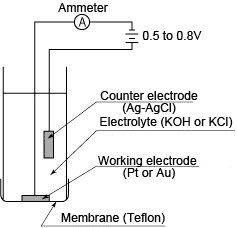
(2) Polarographic method

The sensor construction is almost the same as that of the galvanic cell method. The counter electrode is silver-silver chloride and the working electrode is gold or platinum. When a voltage of 0.5–0.8 V is applied between both electrodes, oxygen that has permeated through the membrane initiates a reduction reaction on the working electrode, causing a polarographic limiting current to flow which is proportional to the oxygen concentration. This method measures the concentration of dissolved oxygen based on this current value.

DO Analyzer Polarographic method

Calibration of the dissolved oxygen analyzer

Calibration of the dissolved oxygen analyzer is performed in the following situations:

– When a new dissolved oxygen sensor is installed
– When the membrane assembly is replaced and/or the electrolyte solution is replaced
– When the sensor has been disassembled and reassembled for maintenance
– When a measuring error after cleaning exceeds the acceptable deviation from the reference method

There are the following methods for calibrating the dissolved oxygen analyzer:

Air calibration:
Performs span calibration in ambient air. This is the most common and easiest way to calibrate the analyzing system, and the method is generally satisfactory. The calibration table lists experimental values at a relative humidity of 70%. It is important to wash any contamination from the sensor membrane, and then wipe off remaining water droplets from the membrane gently with soft paper, etc.
Span calibration in air-saturated water:
This method complies with ISO 5814; perform this calibration if you wish to calibrate the analyzer more accurately.
Zero calibration in sodium sulfite solution:
This calibration takes much time, and is not generally required.
Real solution calibration: Measurement is made using an instrument based on the water being measured and calibration is performed in accordance with the value obtained.

Also Read: Conductivity Analyzer Interview Questions & Answers

Don't Miss Our Updates
Be the first to get exclusive content straight to your email.
We promise not to spam you. You can unsubscribe at any time.
Invalid email address
You've successfully subscribed !

Continue Reading

Oxidation-Reduction Potential (ORP) Sensor Calibration Procedure
Tunable Diode Laser Analyzer Working Principle
Humidity Sensor Working Principle
Dual-beam Non-dispersive Analyzer
Ammonia Gas Detector Working Principle and Calibration
Chlorine dioxide Analyzer Principle
Share This Article
Facebook Whatsapp Whatsapp LinkedIn Copy Link
Share
Leave a Comment

Leave a Reply Cancel reply

Your email address will not be published. Required fields are marked *

Stay Connected

128.3kFollowersLike
69.1kFollowersFollow
210kSubscribersSubscribe
38kFollowersFollow

Categories

Explore More

NDIR Gas Analyser Working Principle
How to Calibrate pH Electrode?
Multi Column Gas Chromatograph
Four Electrode Conductivity Probes Principle
How to Calibrate the Eddy Current Conductivity Meter?
Pulsed Fluorescence SO2, H2S, CS Analyzer Working Principle
Humidity calculator
pH Analyzer Do’s and Don’ts

Keep Learning

Oil in Water Analyzer Principle

Oil in Water Analyzer Working Principle

peak of a chromatogram

Measuring Gases Concentration in Chromatograph

Ozone analyzer principle

Ozone Analyzer Working Principle

Calibration and Troubleshooting of Oxygen Analyzer

Calibration and Troubleshooting of Oxygen Analyzer

Cell Constant in Conductivity Analyzer

What is Cell Constant in Conductivity Analyzer? and its Importance

Conductivity Analyzer Principle

Conductivity Analyzers Interview Questions & Answers

process chemical analyzer calibration

Automated Calibration

What is Chromatography

What is Chromatography ?

Learn More

Electrical Traction Multiple Choice Questions and Answers

Electrical Traction Multiple Choice Questions and Answers

Flow meters Tube Fittings

Sanitary Pipe Fittings for the Instruments

SFC Language in PLC Programming

SFC Language in PLC Programming

Loop Calibrator to Simulate a 4-20 mA Signal

Loop Calibrator to Simulate a 4-20 mA Signal

circuit breaker principle

What is a circuit breaker ?

Argonite/CO2 Flooding System Master & Slave Cylinder Operation

Instrumentation Cable trays in Horizontal Installation

Instrumentation Cable trays Installation in vertical orientation

Internal parts of relief valve

What is a Boiler Pressure Relief Valve?

Menu

  • About
  • Privacy Policy
  • Copyright

Quick Links

  • Learn PLC
  • Helping Hand
  • Part Time Job

YouTube Subscribe

Follow US
All rights reserved. Reproduction in whole or in part without written permission is prohibited.
Welcome Back!

Sign in to your account

Username or Email Address
Password

Lost your password?