Inst ToolsInst ToolsInst Tools
  • Courses
  • Automation
    • PLC
    • Control System
    • Safety System
    • Communication
    • Fire & Gas System
  • Instrumentation
    • Design
    • Pressure
    • Temperature
    • Flow
    • Level
    • Vibration
    • Analyzer
    • Control Valve
    • Switch
    • Calibration
    • Erection & Commissioning
  • Interview
    • Instrumentation
    • Electrical
    • Electronics
    • Practical
  • Q&A
    • Instrumentation
    • Control System
    • Electrical
    • Electronics
    • Analog Electronics
    • Digital Electronics
    • Power Electronics
    • Microprocessor
  • Request
Search
  • Books
  • Software
  • Projects
  • Process
  • Tools
  • Basics
  • Formula
  • Power Plant
  • Root Cause Analysis
  • Electrical Basics
  • Animation
  • Standards
  • 4-20 mA Course
  • Siemens PLC Course
Reading: Ammonia Analyzer Principle
Share
Font ResizerAa
Inst ToolsInst Tools
Font ResizerAa
  • Courses
  • Design
  • PLC
  • Interview
  • Control System
Search
  • Courses
  • Automation
    • PLC
    • Control System
    • Safety System
    • Communication
    • Fire & Gas System
  • Instrumentation
    • Design
    • Pressure
    • Temperature
    • Flow
    • Level
    • Vibration
    • Analyzer
    • Control Valve
    • Switch
    • Calibration
    • Erection & Commissioning
  • Interview
    • Instrumentation
    • Electrical
    • Electronics
    • Practical
  • Q&A
    • Instrumentation
    • Control System
    • Electrical
    • Electronics
    • Analog Electronics
    • Digital Electronics
    • Power Electronics
    • Microprocessor
  • Request
Follow US
All rights reserved. Reproduction in whole or in part without written permission is prohibited.
Inst Tools > Blog > Analyzers > Ammonia Analyzer Principle

Ammonia Analyzer Principle

Last updated: September 5, 2019 9:02 am
Editorial Staff
Analyzers
No Comments
Share
3 Min Read
SHARE

Ammonia/Nitrate Analyzers are based on the principle of diffusion across a gas diffusion membrane coupled with electrical conductivity measurement as first described by Carlson.

The pump directs the sample, caustic, and absorbing solutions into the Membrane Diffusion Cell. Within the cell, the sample is mixed with a caustic solution.

The resulting solution has a pH sufficiently high to convert virtually all of the ammonium ion present in the sample to dissolved ammonia gas, as shown in below equation.

The sample/caustic solution flows past one side of a membrane that is permeable to gases but not to liquids or ionic species.

The dissolved ammonia gas in the sample/caustic mixture will diffuse across the membrane.

Ammonia Analyzer Working

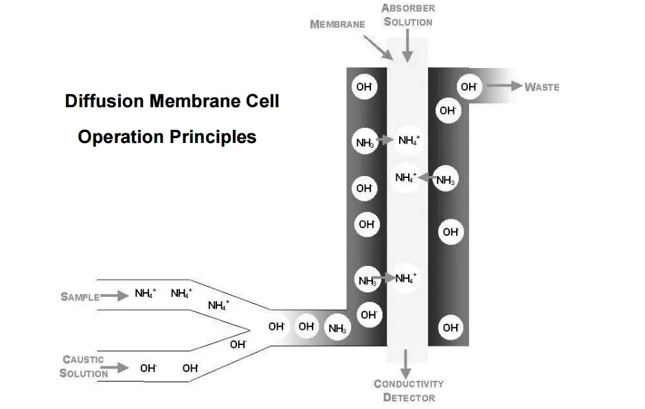
NH4+ ( aq) + OH– (aq ) → NH3( g) + H2O

On the other side of the membrane, a buffered solution absorbs the diffused ammonia gas. The buffered solution then flows into the conductivity detector.

The flow passes through a low volume heat exchanger to establish thermal equilibrium of the solution before it reaches the conductivity cell.

The conductivity cell measures the change in electrical conductance of the absorbing solution. This change is proportional to the concentration of ammonium in the original sample.

Ammonia Analyzer Principle

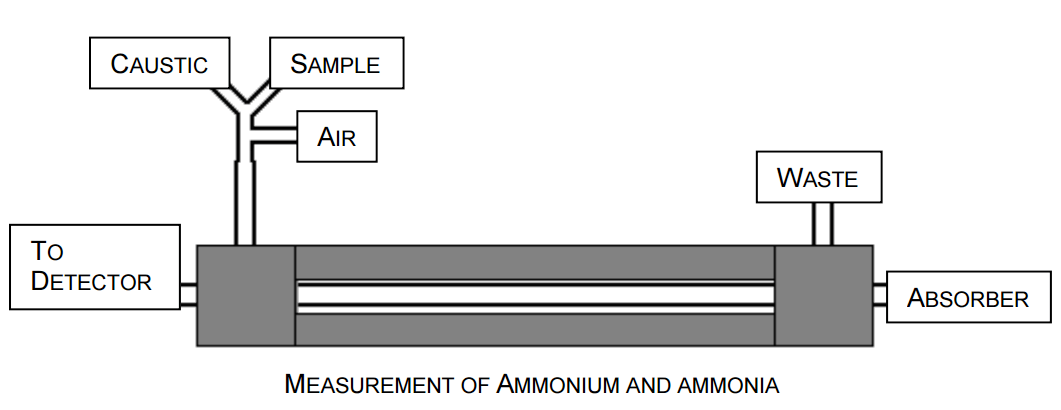
The Diffusion Membrane Cell directs the liquid flow through the tubular membrane to the conductivity detector.

These include the caustic solution, the absorbing solution, the samples, and a recommended air segmentation line.

The caustic and sample solutions are mixed in a tee before entering the gas diffusion cell. This cell is housed in a temperature-controlled enclosure.

Included in this enclosure are two preheating coils used to heat the incoming reagents to a stable temperature.

The temperature should be maintained at least 5°C above the highest expected ambient temperature. Temperature control improves baseline stability, reproducibility and detections limits.

An ultra sensitive conductivity monitoring system is used to detect the ammonia present in the absorbing solution after it passes through the diffusion membrane.

The flow cell is located in a temperature controlled compartment close to the outlet of the diffusion membrane.

The electrical signal obtained from this cell is collected and reported by the conductivity meter which indicates the value of ammonia.

Source : Timberline

Don't Miss Our Updates
Be the first to get exclusive content straight to your email.
We promise not to spam you. You can unsubscribe at any time.
Invalid email address
You've successfully subscribed !

Continue Reading

Fluorescence
Chlorine dioxide Analyzer Principle
Analytical Standards
Difference Between Absolute and Relative Humidity
What is Cell Constant in Conductivity Analyzer? and its Importance
Automated Calibration
Share This Article
Facebook Whatsapp Whatsapp LinkedIn Copy Link
Share
Leave a Comment

Leave a Reply Cancel reply

Your email address will not be published. Required fields are marked *

Stay Connected

128.3kFollowersLike
69.1kFollowersFollow
210kSubscribersSubscribe
38kFollowersFollow

Categories

Explore More

Dissolved Oxygen Analyzer Interview Questions & Answers
Dispersive Spectroscopy
Hair Hydrometer Principle
Oxygen Analyzer Working Principle
Kiln Inlet Gas Analyzer
Dew Point Meter Principle
Silica Analyzer Problems and Troubleshooting Tips
CEMS Principle, Types, Advantages, and Disadvantages

Keep Learning

dissolved-oxygen-probe-calibration-procedure

Dissolved oxygen probe calibration procedure

Turbidity Sensor Calibration Procedure

Turbidity Sensor Calibration Procedure

CO2 Analzer Working Principle

Infrared Non Dispersive CO2 Analyzer Working Principle

conductivity transmitter

Conductivity Transmitter Calibration Procedure

Selection Criteria of PH Analyzer

Selection Criteria of pH Analyzers

How to Calibrate pH Electrode?

How to Calibrate pH Electrode?

Sling Psychrometer Principle

Sling Psychrometer Principle

types-of-total-organic-carbon

Basics of Total Organic Carbon (TOC) Analyzers

Learn More

Selecting a SIS or SIL Level

Importance of Safety Integrity Level

Faceplate in WinCC

Siemens HMI Training – Using UDTs with Faceplates

Battery Interview QuBattery Interview Question and Answersestion and Answers

Battery Interview Question and Answers

Control Valve Testing for Noise Measurement

Control Valve Testing for Noise Measurement

Industrial Automation Acronyms

111 Industrial Automation Acronyms Questions and Answers

Instrument Loop Diagram

How-to Create Instrument Loop Diagram (ILD)?

Impulse Line Purging and Close Coupling

Impulse Line Purging and Close Coupling of Instruments

PLC Programming Software

What Factors Affect the Choice of PLC Programming Software?

Menu

  • About
  • Privacy Policy
  • Copyright

Quick Links

  • Learn PLC
  • Helping Hand
  • Part Time Job

YouTube Subscribe

Follow US
All rights reserved. Reproduction in whole or in part without written permission is prohibited.
Welcome Back!

Sign in to your account

Username or Email Address
Password

Lost your password?