Inst ToolsInst ToolsInst Tools
  • Courses
  • Automation
    • PLC
    • Control System
    • Safety System
    • Communication
    • Fire & Gas System
  • Instrumentation
    • Design
    • Pressure
    • Temperature
    • Flow
    • Level
    • Vibration
    • Analyzer
    • Control Valve
    • Switch
    • Calibration
    • Erection & Commissioning
  • Interview
    • Instrumentation
    • Electrical
    • Electronics
    • Practical
  • Q&A
    • Instrumentation
    • Control System
    • Electrical
    • Electronics
    • Analog Electronics
    • Digital Electronics
    • Power Electronics
    • Microprocessor
  • Request
Search
  • Books
  • Software
  • Projects
  • Process
  • Tools
  • Basics
  • Formula
  • Power Plant
  • Root Cause Analysis
  • Electrical Basics
  • Animation
  • Standards
  • 4-20 mA Course
  • Siemens PLC Course
Reading: PLC Analog Input Card Resolution Effects on Accuracy
Share
Font ResizerAa
Inst ToolsInst Tools
Font ResizerAa
  • Courses
  • Design
  • PLC
  • Interview
  • Control System
Search
  • Courses
  • Automation
    • PLC
    • Control System
    • Safety System
    • Communication
    • Fire & Gas System
  • Instrumentation
    • Design
    • Pressure
    • Temperature
    • Flow
    • Level
    • Vibration
    • Analyzer
    • Control Valve
    • Switch
    • Calibration
    • Erection & Commissioning
  • Interview
    • Instrumentation
    • Electrical
    • Electronics
    • Practical
  • Q&A
    • Instrumentation
    • Control System
    • Electrical
    • Electronics
    • Analog Electronics
    • Digital Electronics
    • Power Electronics
    • Microprocessor
  • Request
Follow US
All rights reserved. Reproduction in whole or in part without written permission is prohibited.
Inst Tools > Blog > PLC Tutorials > PLC Analog Input Card Resolution Effects on Accuracy

PLC Analog Input Card Resolution Effects on Accuracy

Last updated: March 4, 2021 4:21 pm
Editorial Staff
PLC Tutorials
1 Comment
Share
5 Min Read
SHARE

An instrument’s accuracy is limited by its precision. An instrument’s precision is determined by making minute variations in the measured process variable (e.g., pressure, temperature) and then monitoring the instrument’s output for a response.

Contents
PLC Analog Input Card Resolution Effects on AccuracyInstrument Range versus ScaleInstrument Calibration

The smallest magnitude of change an instrument can detect and then reflect at its output is its precision. This precision rating can be listed in percentage of span or in engineering units.

PLC Analog Input Card Resolution Effects on Accuracy

PLC Analog Input Card Resolution Effects on Accuracy | PLC Resolution

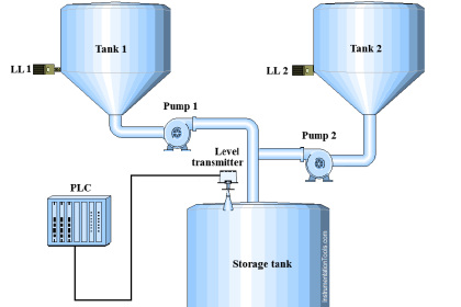
For example, a hypothetical ultrasonic tank level transmitter might have a detection range of 0–12 ft with its output scaled 4–-20 mA, precise to ±0.1 inch.

Precision can be related to the instrument’s resolution. Rather than a smooth movement of the output as the tank level changes, the output will step to a new milliamp value as the level changes in 0.1 inch increments.

The transmitter’s resolution is

12 ft x 12 in/ft x 10 steps/in = 1440 steps across the range.

Therefore, the 4–20 mA signal will change in increments of 16 mA/1440 steps = .01111 mA/step.

In the digital world, bits are units of resolution. The term 12 bit resolution tells us the smallest change of signal magnitude that can be interpreted by the computer or device.

This resolution value relates to the margin of error. Since each device in a system has its own associated resolution (hence, its own margin of error), the overall accuracy of a system is decreased every time a signal is converted or           re-transmitted.

In most cases, the best move is to digitize the signal at the sensor and then transmit the value as a digitized data stream rather than as a pure electrical signal, thus eliminating several layers of conversion.

Most PLCs currently have 12-bit resolution on their analog inputs. This means the analog signal is converted to a 12-bit binary integer.

Once in integer format, the value can be converted to a decimal integer, or hexadecimal, or whatever, for display.

A 4–20 mA signal has a span of 16 mA (20 – 4 =16).

This 16 mA span might represent the 0–100% output of an ultrasonic transmitter or other device.

For an ultrasonic meter with a calibrated range of 12 ft, how much error will the PLC introduce to the system?

12-bit resolution: 4096 divisions

Resolution error: 144 inches/4096 = .0352 inches

Instrument Range versus Scale

There is a difference between an instrument’s design range and its scale.

When an instrument is received, it comes with an inherent range. This range value defines the maximum input span for which the device can provide a linear output.

For example, an ultrasonic level transmitter might have a range of 12 ft.

If we place that transmitter in a 6-ft tank and do not recalibrate it, we will lose resolution.

Its output will only change 50% for a 100% change in tank level.

To rectify this, the unit needs to be recalibrated to provide a 0-–100% change in output for a 0–-50% change in its input, provided the device is scalable to that degree.

Sometimes a device is not scalable beyond, say, 10% of its range. This limit is called rangeability.

Instrument Calibration

An instrument’s scale and its calibrated range are synonymous. Once a scale is decided on, the instrument must be calibrated.

If its range is 0–-550 psig and its scale is 10–-350 psig, its calibrated span is 350 – 10 = 340 psig.

The calibration end points are the zero point and the span point.

The point at which the process is expected to operate is called the set point, though this is not generally part of instrument calibration other than to confirm the anticipated set point is near the center of the calibrated span.

If you liked this article, then please subscribe to our YouTube Channel for PLC and SCADA video tutorials.

You can also follow us on Facebook and Twitter to receive daily updates.

Read Next:

Troubleshooting with Loop Calibrator

4 to 20 mA Conversion Formula

Fieldbus Transmitter Calibration

Split Range Control Application

Reliability of Safety Systems

Don't Miss Our Updates
Be the first to get exclusive content straight to your email.
We promise not to spam you. You can unsubscribe at any time.
Invalid email address
You've successfully subscribed !

Continue Reading

How to Take Program Backup from Physical PLC? – Siemens PLC
Package System Architecture – Control & Instrumentation
PLC SCADA Engineers Interview Questions and Answers
Siemens PLC Comparator Logic
Draw a Ladder Logic to switch ON-OFF a Bulb using a Toggle Switch ?
HMI Screen Design for Hazardous Applications
Share This Article
Facebook Whatsapp Whatsapp LinkedIn Copy Link
Share
1 Comment
  • Victor Toma says:
    June 8, 2018 at 5:54 pm

    “An instrument’s accuracy is limited by its precision” … ????!!!!!! – at the beginning of his article, the author makes a big mess from terms, confusing to each other the accuracy, resolution, precision, sensitivity, etc.

    It is very useful for everybody to review from time to time the terms of JCGM 100 guide.

    Reply

Leave a Reply Cancel reply

Your email address will not be published. Required fields are marked *

Stay Connected

128.3kFollowersLike
69.1kFollowersFollow
210kSubscribersSubscribe
38kFollowersFollow

Categories

Explore More

Animation of Electromagnetic Relay
PLC based Door Open and Closing System
Types of SCADA System Architecture
Toggle Switch & Sensor: Conveyor and Puncher PLC Program
What is Contextual HMI? – HMI Screens on a Mobile or Tablet
Various Types of Delta PLC used in Industrial Automation
PLC Ladder Logic for Sensor Scaling with Offset
Motor ON OFF Logic in PLC

Keep Learning

Boolean Algebra to PLC Logic

From Boolean Algebra to PLC Logic

Door Locking System - PLC Applications Examples

Door Locking System – PLC Applications Examples

PLC SCADA Water Pump

PLC Program for Controlling a Water Pump with 3 Power Sources

Siemens micro memory card

Micro Memory Card (MMC) in Siemens PLC

Concept of DCS in Industrial Automation

Concept of DCS in Industrial Automation

Static and Temp Variables in PLC

Static and Temp Variables in PLC

PLC Counters Simulation

Example of Using a Counter in Omron PLC

Sticker machine with weighing PLC logic

Product Sticker Machine with Weighing PLC Program

Learn More

What is a Tachometer

What is a Tachometer? – Types, Working Principle

Battery Interview QuBattery Interview Question and Answersestion and Answers

Battery Terminology

Industrial motor control using PLC instruction list programming

PLC Instruction List for Motor Reverse and Forward Direction

Compare Serial and Parallel Communication

Difference Between Serial and Parallel Communication

Determine the Problems with the Level Transmitter and Gauge

Determine the Problems with Level Transmitter and Gauge

What is Ladder Diagram Programming ?

Differential Pressure Gauge Principle

Piston Type Differential Pressure Gauge Principle

Logic Gates Symbols & Truthtables

Logic Gates Animation

Menu

  • About
  • Privacy Policy
  • Copyright

Quick Links

  • Learn PLC
  • Helping Hand
  • Part Time Job

YouTube Subscribe

Follow US
All rights reserved. Reproduction in whole or in part without written permission is prohibited.
Welcome Back!

Sign in to your account

Username or Email Address
Password

Lost your password?