Seven Basic Logic Gates
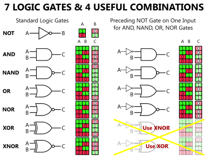
Digital electronics relies on the actions of just seven types of logic gates, called AND, OR, NAND (Not AND), NOR (Not OR), XOR (Exclusive OR) XNOR (Exclusive NOR) and NOT.
Because, in binary logic there are only two states, 1 and 0 or ‘on and off,’ NOT in the world of binary logic therefore means ‘the opposite of’. If something is not 1 it must be 0, if it is not on, it must be off. So NAND (not AND) simply means that a NAND gate performs the opposite function to an AND gate.
A logic gate is a small transistor circuit, basically a type of amplifier, which is implemented in different forms within an integrated circuit. Each type of gate has one or more (most often two) inputs and one output.
The principle of operation is that the circuit operates on just two voltage levels, called logic 0 and logic 1. When either of these voltage levels is applied to the inputs, the output of the gate responds by assuming a 1 or a 0 level, depending on the particular logic of the gate. The logic rules for each type of gate can be described in different ways, by a written description of the action, by a truth table, or by a Boolean algebra statement.
Boolean statements use letters from the beginning of the alphabet, such as A, B, C etc. to indicate inputs, and letters from the second half of the alphabet, very commonly X or Y and sometimes Q or P to label an output. The letters have no meaning in themselves, other than just to label the various points in the circuit. The letters are then linked by a symbol indicating the logical action of the gate.
The • symbol indicates AND although in many cases the • may be omitted. (A•B may also be written as AB or A.B)
+ indicates OR
⊕ indicates XOR (Exclusive OR)
Although the symbols • and + are the same as those used in normal algebra to indicate product (multiplication) and sum (addition) respectively, in binary logic the + symbol does not exactly correspond to sum. In digital logic 1 + (OR) 1 = 1, but the binary sum of 1 + 1 = 102, therefore in digital logic + must always be considered as OR.
Three further types of logic gate give an output that is an inverted version of the three basic gate functions listed above, and these are indicated by a bar drawn above a statement using the AND, OR, or XOR symbols to indicate NAND, NOR and XNOR.
A•B means A AND B but A•B means A NAND B
For example:
An AND gate gives an output of logic 1 when input A AND input B are at logic 1, but a NAND gate would give a logic 0 output for the same input conditions. Also where the AND gate gives a logic zero for a particular input combination, the NAND gate would give a logic 1. The ‘N’ in the gate’s name, or the bar above the Boolean expression therefore indicates that the output logic is ‘inverted’. In digital logic NAND is ‘NOT’ AND, or the opposite of AND. Similarly NOR is ‘NOT’ OR, and XNOR is ‘NOT’ XOR.
The final gate type, the NOT gate or inverter is a single input gate that has an output having the opposite logic state, or the inverse of the input.
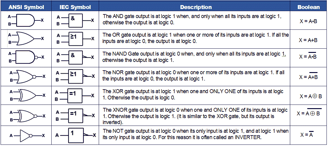
Below table shows each of the seven basic logic gates, which may be illustrated by either the traditional “Distinctive Shape” ANSI symbol or the newer rectangular IEC symbol, and a written description of its logic function compared with its Boolean equation.
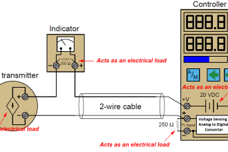
 Also Read: Why we use a Current Loop